Cable adjusting unit
a cable adjuster and cable technology, applied in the direction of bicycle brakes, cycle equipment, braking systems, etc., can solve the problem and achieve the effect of limited position of the cable adjuster on the bicycl
- Summary
- Abstract
- Description
- Claims
- Application Information
AI Technical Summary
Benefits of technology
Problems solved by technology
Method used
Image
Examples
second embodiment
[0079]Referring now to FIG. 9, a cable adjusting unit 212 in accordance with a second embodiment will now be explained.
[0080]In view of the similarity between the first and second embodiments, the parts of the second embodiment that are identical to the parts of the first embodiment will be given the same reference numerals as the parts of the first embodiment. In any event, the descriptions of the parts of the second embodiment that are substantially identical to the parts of the first embodiment may be omitted for the sake of brevity. However, it will be apparent to those skilled in the art from this disclosure that the descriptions and illustrations of the first embodiment also apply to this second embodiment, except as discussed and / or illustrated herein.
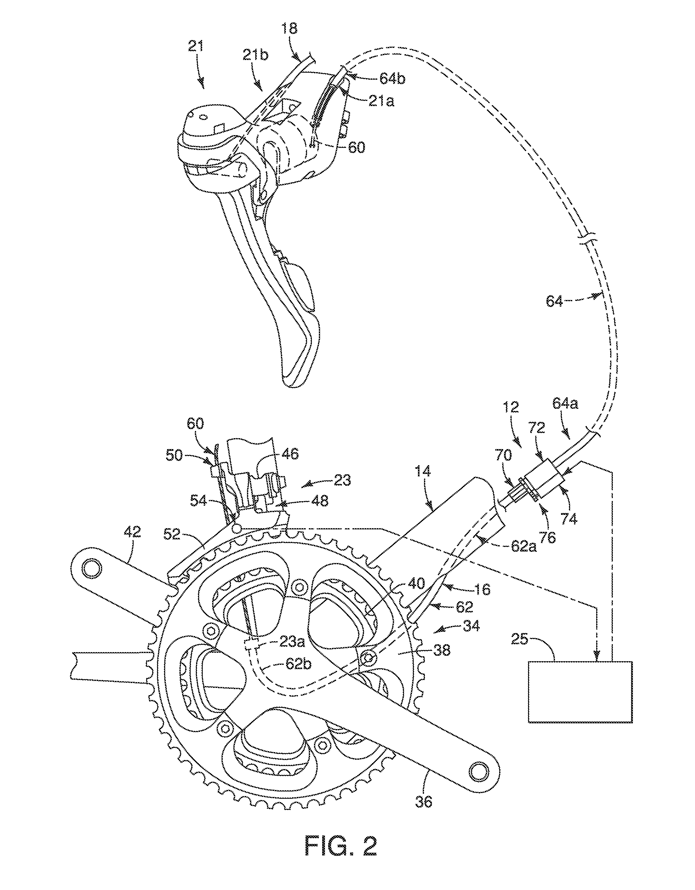
[0081]Basically, the cable adjusting unit 212 adjusts the overall effective length of the first and second outer cases 62 and 64 by moving the adjacent ends 62a and 64a of the first and second outer cases 62 and 64 away from eac...
third embodiment
[0089]Referring now to FIG. 10, a cable adjusting unit 312 in accordance with a third embodiment will now be explained.
[0090]In view of the similarity between the first and third embodiments, the parts of the third embodiment that are identical to the parts of the first embodiment will be given the same reference numerals as the parts of the first embodiment. In any event, the descriptions of the parts of the third embodiment that are substantially identical to the parts of the first embodiment may be omitted for the sake of brevity. However, it will be apparent to those skilled in the art from this disclosure that the descriptions and illustrations of the first embodiment also apply to this third embodiment, except as discussed and / or illustrated herein.
[0091]Basically, the cable adjusting unit 312 adjusts the overall effective length of the first and second outer cases 62 and 64 by moving the adjacent ends 62a and 64a of the first and second outer cases 62 and 64 away from each ot...
fourth embodiment
[0100]Referring now to FIG. 11, a cable adjusting unit 412 in accordance with a fourth embodiment will now be explained.
[0101]In view of the similarity between the first and fourth embodiments, the parts of the fourth embodiment that are identical to the parts of the first embodiment will be given the same reference numerals as the parts of the first embodiment. In any event, the descriptions of the parts of the fourth embodiment that are substantially identical to the parts of the first embodiment may be omitted for the sake of brevity. However, it will be apparent to those skilled in the art from this disclosure that the descriptions and illustrations of the first embodiment also apply to this fourth embodiment, except as discussed and / or illustrated herein.
[0102]Basically, the cable adjusting unit 412 adjusts the overall effective length of the first and second outer cases 62 and 64 by moving the adjacent ends 62a and 64a of the first and second outer cases 62 and 64 away from ea...
PUM
 Abstract
Description
Claims
Application Information
 - R&D
- Intellectual Property
- Life Sciences
- Materials
- Tech Scout
- Unparalleled Data Quality
- Higher Quality Content
- 60% Fewer Hallucinations
Browse by: Latest US Patents, China's latest patents, Technical Efficacy Thesaurus, Application Domain, Technology Topic, Popular Technical Reports.
© 2025 PatSnap. All rights reserved.Legal|Privacy policy|Modern Slavery Act Transparency Statement|Sitemap|About US| Contact US: help@patsnap.com


