Electronic device

a technology of electronic devices and projectors, applied in optics, instruments, color televisions, etc., can solve the problems of projectors that cannot be installed in the same place, projectors tend to be larger, and projectors that cannot be moved

Inactive Publication Date: 2014-10-16
FUNAI ELECTRIC CO LTD
View PDF12 Cites 4 Cited by
  • Summary
  • Abstract
  • Description
  • Claims
  • Application Information

AI Technical Summary

Benefits of technology

[0007]With a projector, however, the projector unit must be kept at a constant height or higher. If the projector unit is disposed in the same housing as the visible camera as in the above-mentioned Patent Literature 1, then the installation position of the projector unit is limited, and the projector tends to become larger. Also, if the projector unit is fixed in the housing as in the above-mentioned Patent Literature 1, then the size of the image projected by the projector unit on a projection surface will be fixed by the device. Furthermore, the places where the projector can be installed are limited.

Problems solved by technology

If the projector unit is disposed in the same housing as the visible camera as in the above-mentioned Patent Literature 1, then the installation position of the projector unit is limited, and the projector tends to become larger.
Furthermore, the places where the projector can be installed are limited.

Method used


Image

  • Electronic device
  • Electronic device
  • Electronic device

Examples


first embodiment

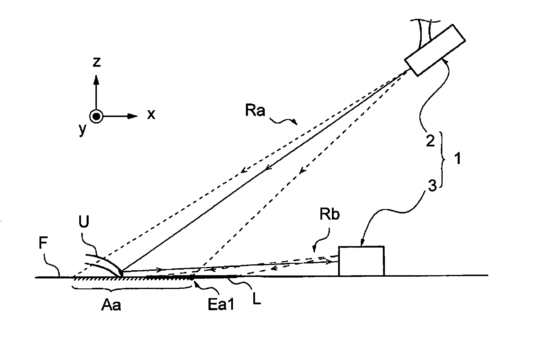
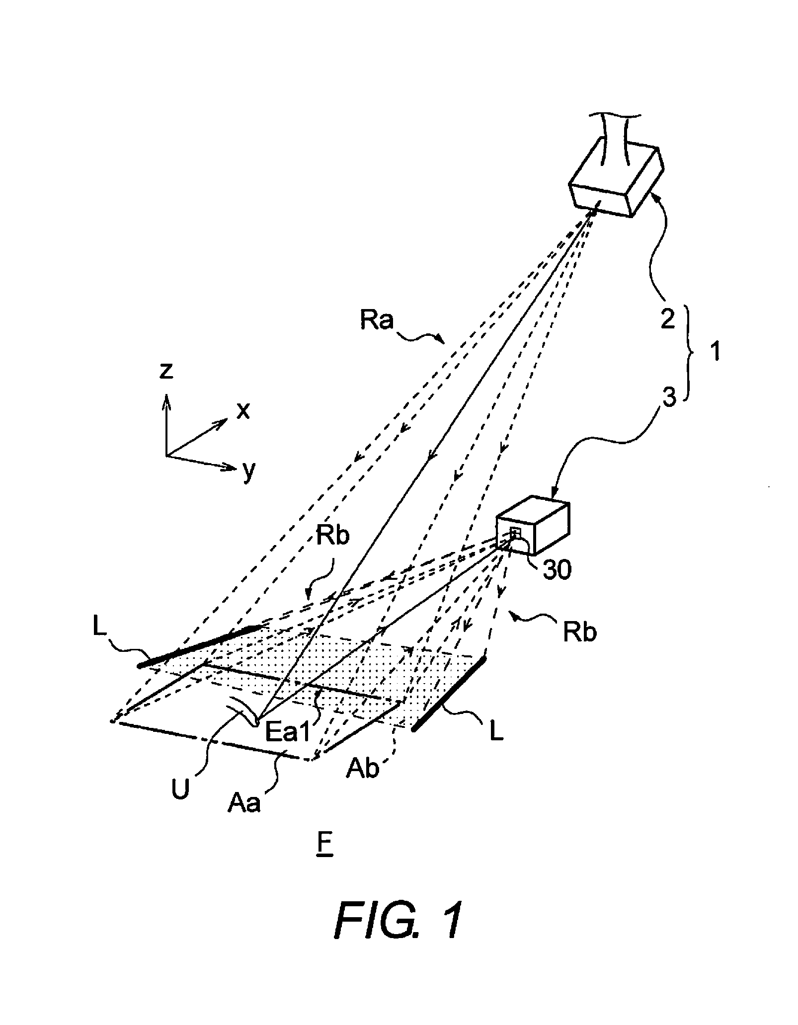
[0032]Referring initially to FIG. 1, a projector 1 is illustrated in accordance with a first embodiment. The projector 1 is a laser beam scanning type of projection device with a VUI (Virtual User Interface) function. The projector 1 is an example of an electronic device that can be used as an input device with its VUI function. The VUI function is a virtual input interface with which the user can make inputs to a projected image (such as an image of a keyboard or an input panel) projected onto a projection surface F.

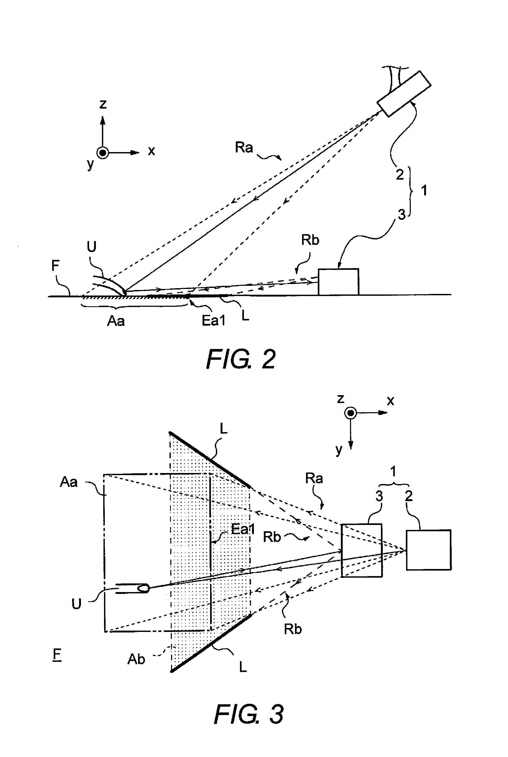
[0033]FIG. 1 is a perspective view of the appearance of the projector 1. FIG. 2 is a side elevational view illustrating the optical path of the projector 1. FIG. 3 is a top plan view illustrating the optical path of the projector 1. In the following (not just in this embodiment), the x direction and y direction refer to directions parallel to the projection surface F, while the z direction refers to the normal direction of the projection surface F. The x, y, and z direc...

second embodiment

[0096]Referring now to FIG. 12, a projector 1 in accordance with a second embodiment will now be explained. In view of the similarity between the first and second embodiments, the parts of the second embodiment that are functionally identical to the parts of the first embodiment will be given the same reference numerals as the parts of the first embodiment. Moreover, the descriptions of the parts of the second embodiment that are identical to the parts of the first embodiment may be omitted for the sake of brevity. FIG. 12 is a perspective view of the appearance of the projector 1 in accordance with the second embodiment. In FIG. 12, the scanning laser beam Ra, the notification light Rb, and their reflected lights are not depicted, in order to make it easier to understand the main components.

[0097]As shown in FIG. 12, in the second embodiment definition light Rc for defining the projection region Aa is projected from the projector unit 2, and this projected image (e.g., the spots S1...

third embodiment

[0124]Referring now to FIG. 16, a sensor unit 3 in accordance with a third embodiment will now be explained. In view of the similarity between the first to third embodiments, the parts of the third embodiment that are identical to the parts of the first and second embodiments will be given the same reference numerals as the parts of the first and second embodiments. Moreover, the descriptions of the parts of the third embodiment that are identical to the parts of the first and second embodiments may be omitted for the sake of brevity.

[0125]In the third embodiment, the sensor unit 3 includes a mechanism for automatically adjusting the installation position and orientation of the sensor unit 3 based on the reflected light detection result produced by the photodetector 31. Everything else is the same as in the first or second embodiment. In the following discussion, components that are the same as in the first embodiment will be numbered the same and not described again.

[0126]FIG. 16 i...


PUM


Abstract

An electronic device includes a projection unit and a detection unit. The projection unit is configured to project light in a projection region on a projection surface. The detection unit is disposed away from the projection unit. The detection unit includes a photodetector and a notification light emitter. The photodetector is configured to detect reflected light of the light from the projection unit within a detection region. The notification light emitter is configured to emit to the projection surface notification light for setting a position of the projection region within the detection region of the photodetector.

Description

CROSS-REFERENCE TO RELATED APPLICATIONS[0001]This application claims priority to Japanese Patent Application No. 2013-084058 filed on Apr. 12, 2013. The entire disclosure of Japanese Patent Application No. 2013-084058 is hereby incorporated herein by reference.BACKGROUND[0002]1. Field of the Invention[0003]The present invention generally relates to an electronic device. More specifically, the present invention relates to an electronic device that detects reflected light of light that has been projected.[0004]2. Background Information[0005]Projectors that project an image onto a screen, a wall, a desktop, or another such projection surface are well-known in the art. Various kinds of devices that make use of a projector are also developed (see Japanese Unexamined Patent Application Publication No. 2012-108233 (Patent Literature 1), for example.[0006]This Patent Literature 1 discloses a projector with a VUI (Virtual User Interface). With this projector, a projector unit, a light projec...

Claims


Application Information

Patent Timeline
Patent Type & Authority Applications(United States)
IPC IPC(8): G01B11/14
CPCG01B11/14G06F3/0418G06F3/0425H04N9/3129H04N9/3194H04N2201/0452G03B21/145
Inventor YAMAGIWA, DAISUKE
Owner FUNAI ELECTRIC CO LTD
Why Eureka
Try Eureka