Stitching apparatus and method of use

a technology of stitching apparatus and thread, applied in the field of sewing and embroidery, can solve the problems of bobbin threads that cannot be replaced bobbin threads that cannot be used, etc., and achieve the effect of reducing the complexity of the stitching process, reducing breakage and thread depletion

Inactive Publication Date: 2014-08-07
MCCUE FAMILY TRUST
View PDF1 Cites 8 Cited by
  • Summary
  • Abstract
  • Description
  • Claims
  • Application Information

AI Technical Summary

Benefits of technology

[0006]It is the object of the present invention to address the challenge presented by a traditional spooled bobbin sewing or embroidery machine system. With the present invention, large spools of material can be used and driven into position in a sewing, embroidery or other stitching machine, decreasing the complexity of the stitching process and reducing breakage and thread depletion. The invention is a stitching apparatus for forming a stitch in a piece of fabric or other material suitable to receive a stitch, the apparatus generally comprised of an upper thread feeding assembly, a lower thread feeding assembly, a stitching surface area and an activation assembly, wherein the activation assembly bonds the upper thread to the lower thread at the stitching surface area. The invention further comprises a method for forming a stitch in a piece of fabric or other material suitable to receive a stitch wherein an upper thread is passed through a stitching surface, a lower thread is positioned on the stitching surface, the upper and lower threads are fused and the upper thread is passed back through the stitching surface.

Problems solved by technology

The problem with this traditional approach is that the bobbin spool, having a limited amount of thread, must be constantly replaced.
Since the upper thread doesn't have any limitations, large spools or skeins can be utilized for longer sewing times. Bobbin threads are also subject to breakage and the casing becomes filled with lint and thread scraps.

Method used


Image

  • Stitching apparatus and method of use
  • Stitching apparatus and method of use
  • Stitching apparatus and method of use

Examples


second embodiment

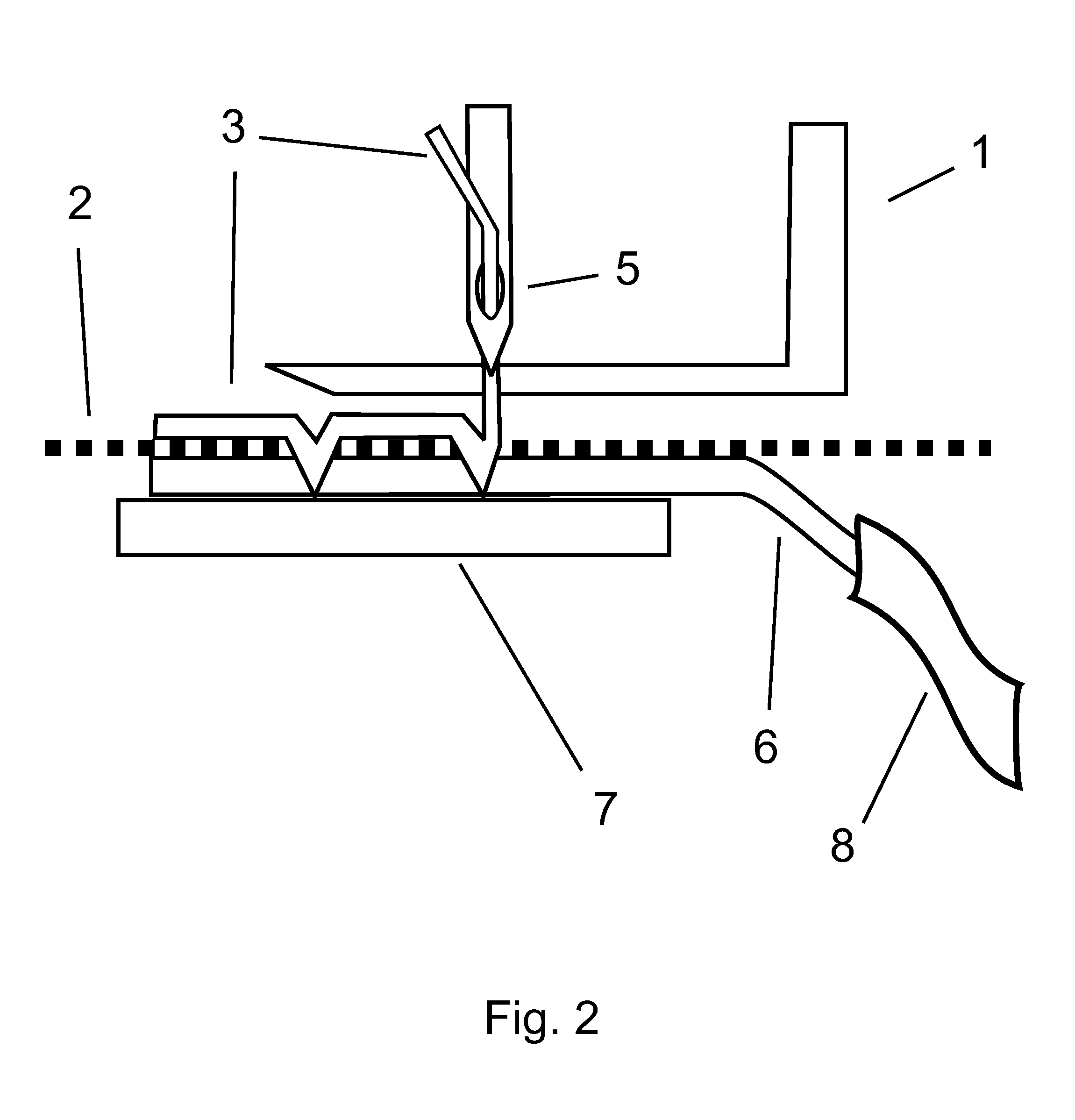
[0018]Turning to FIG. 3, in the present invention, the upper thread 3 is a traditional thread such as cotton, synthetic or blends of multifilament configuration fed through needle tip 5 and the lower thread 6 is a self-bonding, phase change material capable of changing phases when heated and / or cooled. Examples of a suitable lower thread material include but are not limited to polyester, nylon, acrylic, copolymer or mixtures thereof. The upper thread feeding assembly uses a pressure foot 1 to move the move the stitching surface 2 through the stitching apparatus 11 and a guide plate 7 to move the lower thread material 6 into position on the stitching surface 2. The lower thread material 6 is fed into the stitching area using container 8 and an activator assembly activates the lower thread material 6. In the preferred embodiment, the activator assembly is a needle with a heating apparatus 9 located within the tip of the container 8. The heating apparatus 9 heats the lower thread mater...

third embodiment

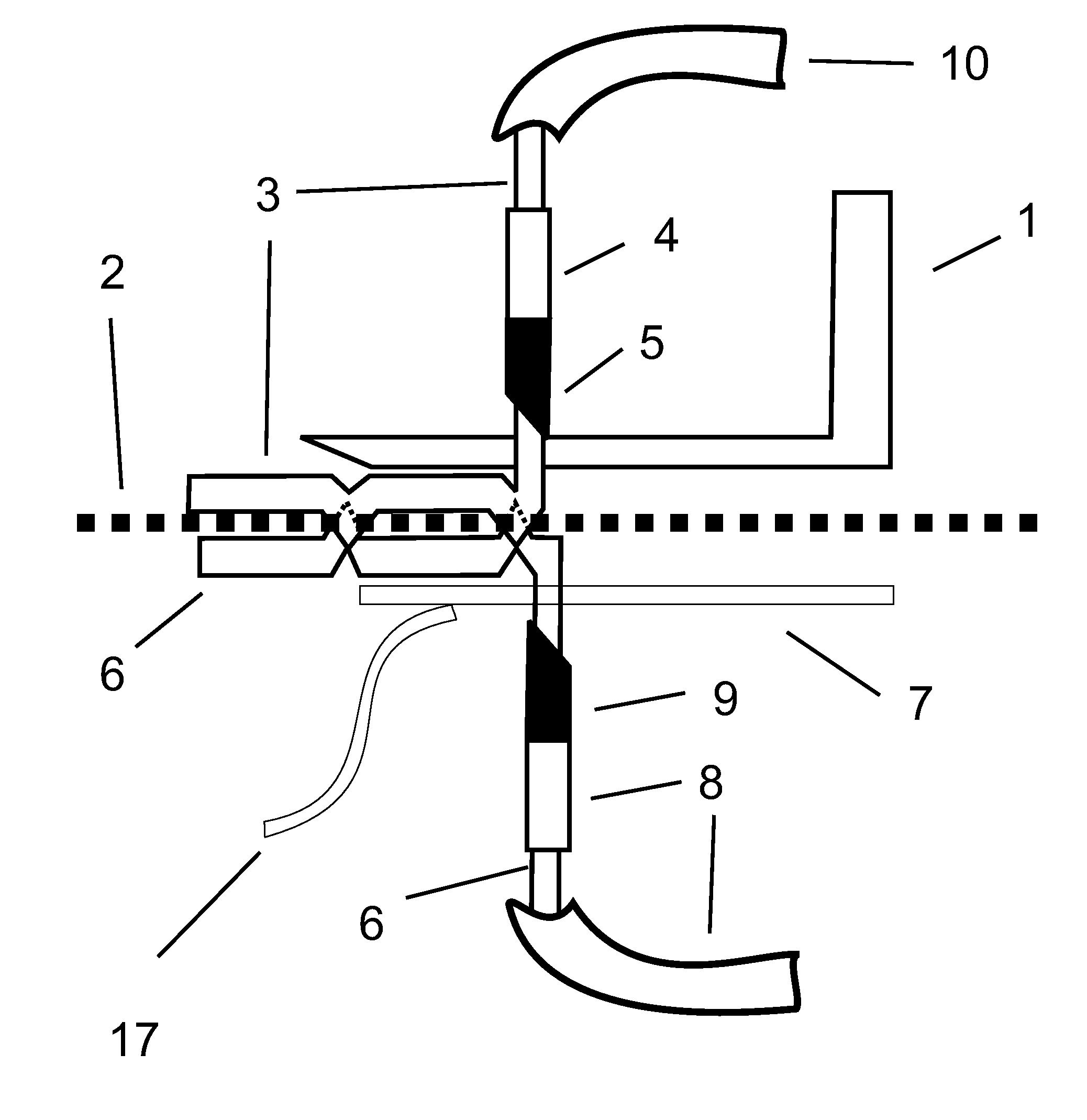
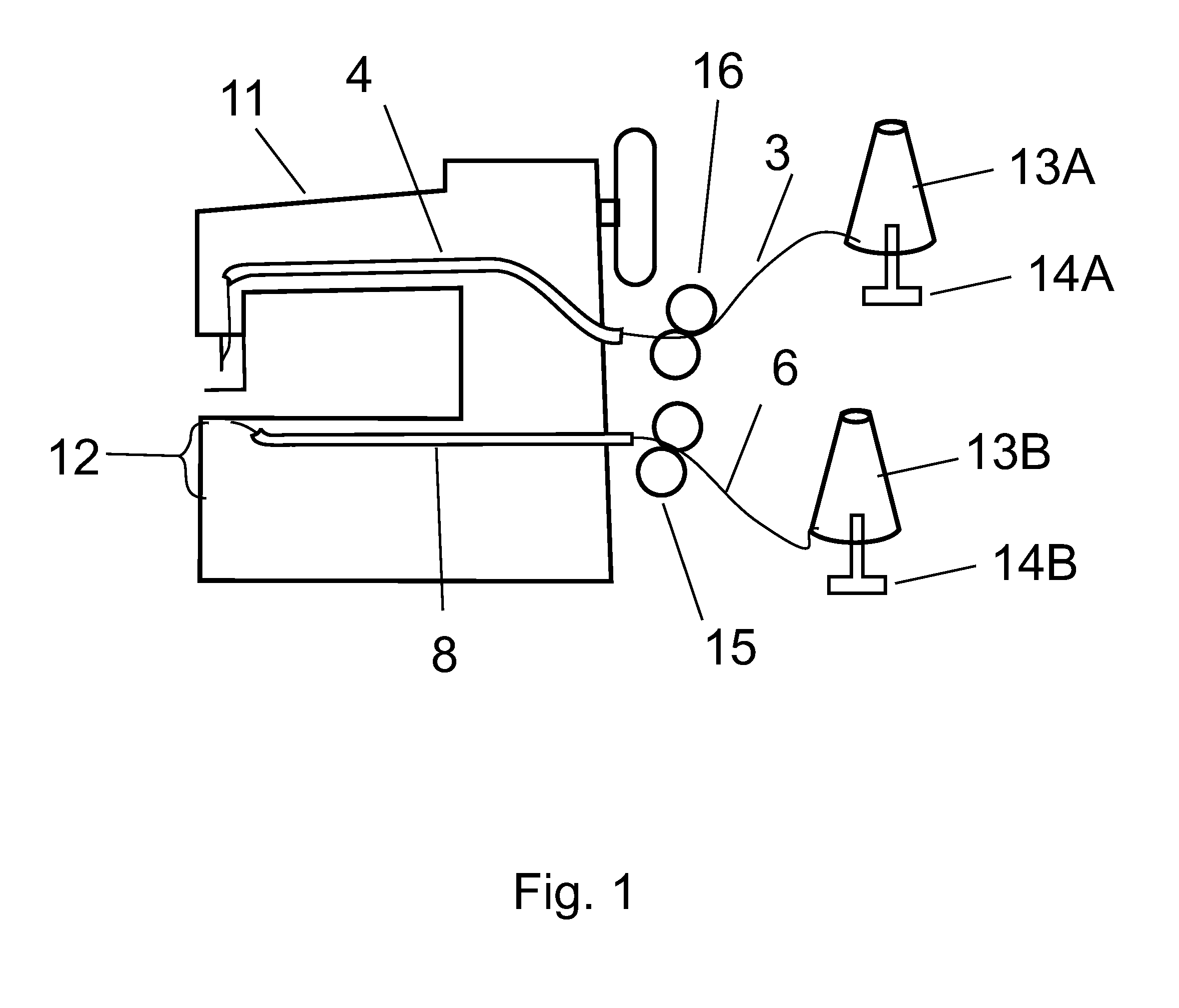
[0019]Turning to FIG. 4, in the present invention the upper thread 3 is a self-bonding, phase change material capable of changing phases when heated and / or cooled fed through a needle and the lower thread 6 is a self-bonding, phase change material capable of changing phases when heated and / or cooled. Examples of suitable upper and lower thread materials include but are not limited to polyester, nylon, acrylic, copolymer or mixtures thereof. The upper thread feeding assembly uses a pressure foot 1 to move the move the stitching surface 2 through the stitching apparatus and a guide plate 7 to move the lower thread material 6 into position on the stitching surface 2. The lower thread material 6 is fed into the stitching area using container 8. In the preferred embodiment, the activator assembly is a needle with heating apparatus 5 located within the tip of the container 4. The heating apparatus 5 heats the upper thread material 3 and lower thread material 6, thereby fusing the two mate...

fourth embodiment

[0020]Turning to FIG. 5, in the present invention, the upper thread 3 is a self-bonding, phase change material capable of changing phases when heated and / or cooled fed through a needle and the lower thread 6 is a self-bonding, phase change material capable of changing phases when heated and / or cooled. Examples of a suitable upper and lower thread materials include but are not limited to polyester, nylon, acrylic, copolymer or mixtures thereof. The upper thread feeding assembly uses a pressure foot 1 to move the move the stitching surface 2 through the stitching apparatus and a guide plate 7 to move the lower thread material 6 into position on the stitching surface 2. The lower thread material 6 is fed into the stitching area using container 8. In the preferred embodiment, the activator assembly is a plurality of needles, one for the upper thread and one for the lower thread, with a heating apparatus 5 located within the tip of the container 4 and a heating apparatus 9 located within...


PUM

PropertyMeasurementUnit
surface areaaaaaaaaaaa
pressureaaaaaaaaaa
phase changeaaaaaaaaaa

Abstract

The present invention is a stitching apparatus and method of use wherein large spools of material can be used and driven into position in a sewing, embroidery or other stitching machine, thereby decreasing the complexity of the stitching process and reducing breakage and thread depletion. The apparatus generally comprises an upper thread feeding assembly, a lower thread feeding assembly, a stitching surface area and an activation assembly, wherein the activation assembly bonds the upper thread to the lower thread at the stitching surface area.

Description

RELATED APPLICATIONS[0001]This application claims priority to U.S. Provisional Application No. 61 / 760,548 filed Feb. 4, 2013. The entire contents of the above application are hereby incorporated by reference as though fully set forth herein.FIELD[0002]The present invention relates to the field of sewing and embroidery. More specifically, the present invention relates to a new stitching apparatus and method of use for stitching or sewing with both traditional and reactive threads and materials.BACKGROUND[0003]Traditionally, sewing and embroidery requires the use of an upper and lower thread. The upper thread is pushed through a needle where it is moved up and down through the sewing foot and fabric being sewn. The lower thread is wound on a spool called a bobbin. The entire bobbin assembly consists of housing, rotating hook, spool and casing. The upper thread is moved downward into the bobbin case, where the hook grabs the thread and feeds it around the spool to form a loop, which is...

Claims


Application Information

Patent Timeline
Patent Type & Authority Applications(United States)
IPC IPC(8): D05B17/00
CPCD05B17/00B29C65/18B29C65/62B29C65/72B29C66/43B29C66/729B29C66/8322
Inventor MCCUE, GEOFF
Owner MCCUE FAMILY TRUST
Why Eureka
Try Eureka