Transmission device, transmission method, reception device, reception method, and transmission/reception system

a transmission device and transmission method technology, applied in the field of transmission devices, can solve the problems of difficult to realize such an application, inability to perform high-quality reproduction using the high-quality clock source provided in the repeater device, and inability to achieve high-quality content reproduction, etc., to achieve the effect of easy display and high-quality content reproduction

Active Publication Date: 2014-08-07
SONY CORP
View PDF3 Cites 10 Cited by
  • Summary
  • Abstract
  • Description
  • Claims
  • Application Information

AI Technical Summary

Benefits of technology

[0036]According to the present technique, high-quality content reproduction can be performed in the sink (repeater) device, without the use of any additional line. Also, according to the present technique, content from more than one source device can be easily displayed simultaneously on divided screens on the sink device side.

Problems solved by technology

According to the above described HDMI Specification, however, a clock generated by an inexpensive clock source included in the source device needs to be used in reproduction, and reproduction using a clock generated by the high-performance clock source in the repeater device cannot be performed.
In view of this, it is difficult to realize such an application.
However, in a connection according to the HDMI Specification, high-quality reproduction using the high-quality clock source provided in a repeater device cannot be performed.

Method used


Image

  • Transmission device, transmission method, reception device, reception method, and transmission/reception system
  • Transmission device, transmission method, reception device, reception method, and transmission/reception system
  • Transmission device, transmission method, reception device, reception method, and transmission/reception system

Examples


embodiment

1. Embodiment

Configuration of an AV System

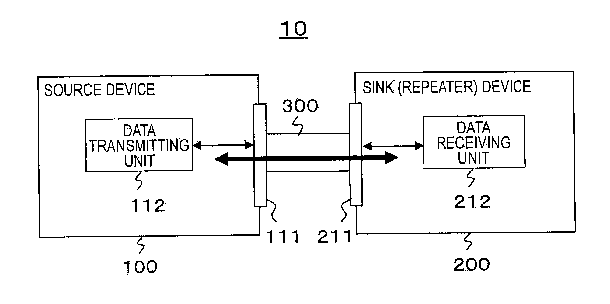
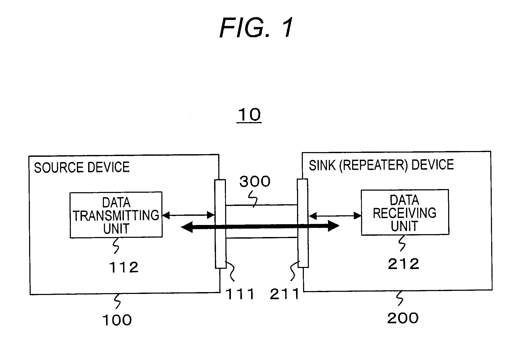
[0051]FIG. 1 shows an example configuration of an AV (Audio and Visual) system 10. This AV system 10 is formed with a source device 100 and a sink (repeater) device 200 that are connected to each other. The source device 100 is an AV source such as a game machine, a disk player, a set-top box, a digital camera, or a mobile phone. The sink (repeater) device 200 is a television receiver or a projector, for example.

[0052]The source device 100 and the sink (repeater) device 200 are connected to each other via a cable (HDMI cable) 300. The source device 100 includes a connector unit 111 having a data transmitting unit 112 connected thereto. The sink device 200 includes a connector unit 211 having a data receiving unit 212 connected thereto. One end of the cable 300 is connected to the connector unit 111 of the source device 100, and the other end of the cable 300 is connected to the connector unit 211 of the sink (repeater) device 200.

[0053]The d...


PUM


Abstract

High-quality content reproduction is to be realized.A transmission clock is supplied from a sink (repeater) device to a source device via a clock signal line. The source device sends content data to the sink (repeater) device via a predetermined number of differential signal lines in synchronization with the transmission clock supplied from the sink (repeater) device. High-quality content reproduction can be performed in the sink (repeater) device, without the use of any additional lines other than the differential signal lines and the clock signal line. For example, upon receipt of a transmission clock supply request from the source device, the sink (repeater) device supplies the transmission clock to the source device.

Description

TECHNICAL FIELD[0001]The present technique relates to a transmission device, a transmission method, a reception device, a reception method, and a transmission / reception system, and more particularly, to a transmission device and the like that enable high-quality content reproduction on the reception side.BACKGROUND ART[0002]In recent years, AV (Audio / Visual) devices that involve digital signals such as audio signals and video signals have spread, and there are various kinds of interfaces suggested for transmitting digital signals between such AV devices. Those interfaces include widely-known ones compliant with the IEEE (Institute of Electrical and Electronics Engineers) 1394 standards, the HDMI (High-Definition Multimedia Interface) standards (HDMI being a registered trade name), and the like.[0003]According to the HDMI Specification, a TMDS clock synchronized with TMDS (Transition Minimized Differential Signaling) data is normally transmitted from a source device to a sink (repeat...

Claims


Application Information

Patent Timeline
Patent Type & Authority Applications(United States)
IPC IPC(8): H04N5/38
CPCH04N5/38H04N21/4302H04N21/43635G09G5/006G09G5/008G09G5/12G09G5/14G09G2370/04G09G2370/06G09G2370/12G09G2370/20
Inventor TOBA, KAZUAKIICHIMURA, GEN
Owner SONY CORP
Why Eureka
Try Eureka