
System and method for remotely monitoring machines

a technology for remotely monitoring machines and monitoring systems, applied in data switching networks, wireless architecture usage, transportation and packaging, etc., can solve problems such as time-consuming and laborious tasks, failures of high critical failures, and failures to meet the needs of immediate attention,

Inactive Publication Date: 2014-08-07
CATERPILLAR GLOBAL MINING LLC
View PDF18 Cites 31 Cited by
  • Summary
  • Abstract
  • Description
  • Claims
  • Application Information

AI Technical Summary

Benefits of technology

The patent describes a method, system, and computer software for remotely monitoring machines using a portable device over a wireless network. This allows for quick detection and management of machine faults, with information displayed on the portable device based on the severity of the fault. The technical effects of this invention include improved efficiency and accuracy in identifying and managing machine faults, as well as improved overall machine monitoring and management.

Problems solved by technology

All of these machines may encounter one or more faults and failures associated with them.
Some of these failures may not be very critical for the machine's performance, whereas some faults may be highly critical for the machine's performance.
Such high critical failures may need immediate attention by an operator and / or service personnel in order to rectify the fault and / or replace a component within the machine which has failed.
However, physically connecting every machine in the worksite may be a time consuming and tedious task.
Also, the service personnel may not know which machine has high criticality failures and which machine needs to be serviced on priority, thereby resulting in undesired downtime of machines.

Method used


Image

  • System and method for remotely monitoring machines
  • System and method for remotely monitoring machines
  • System and method for remotely monitoring machines

Examples


Embodiment Construction

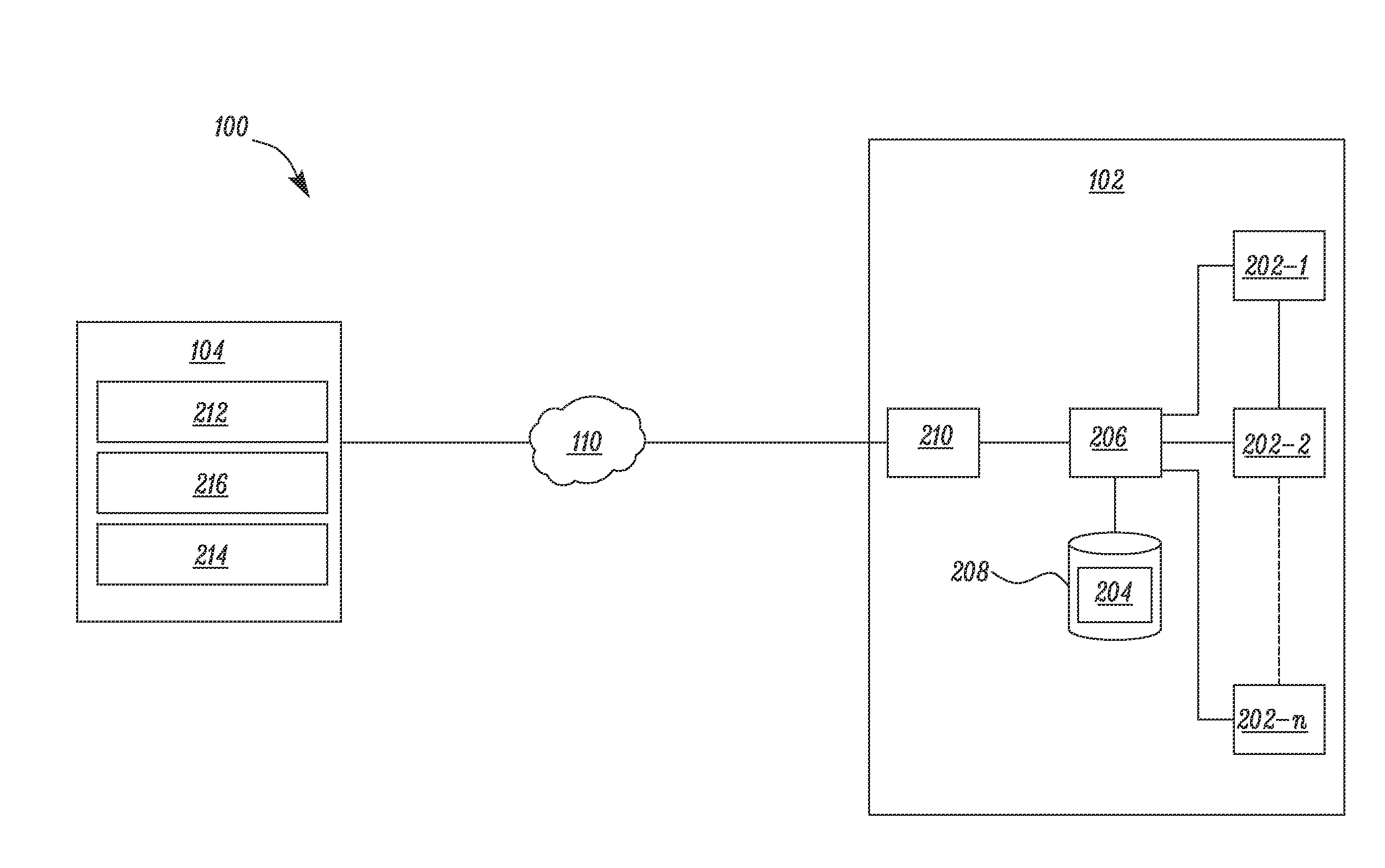
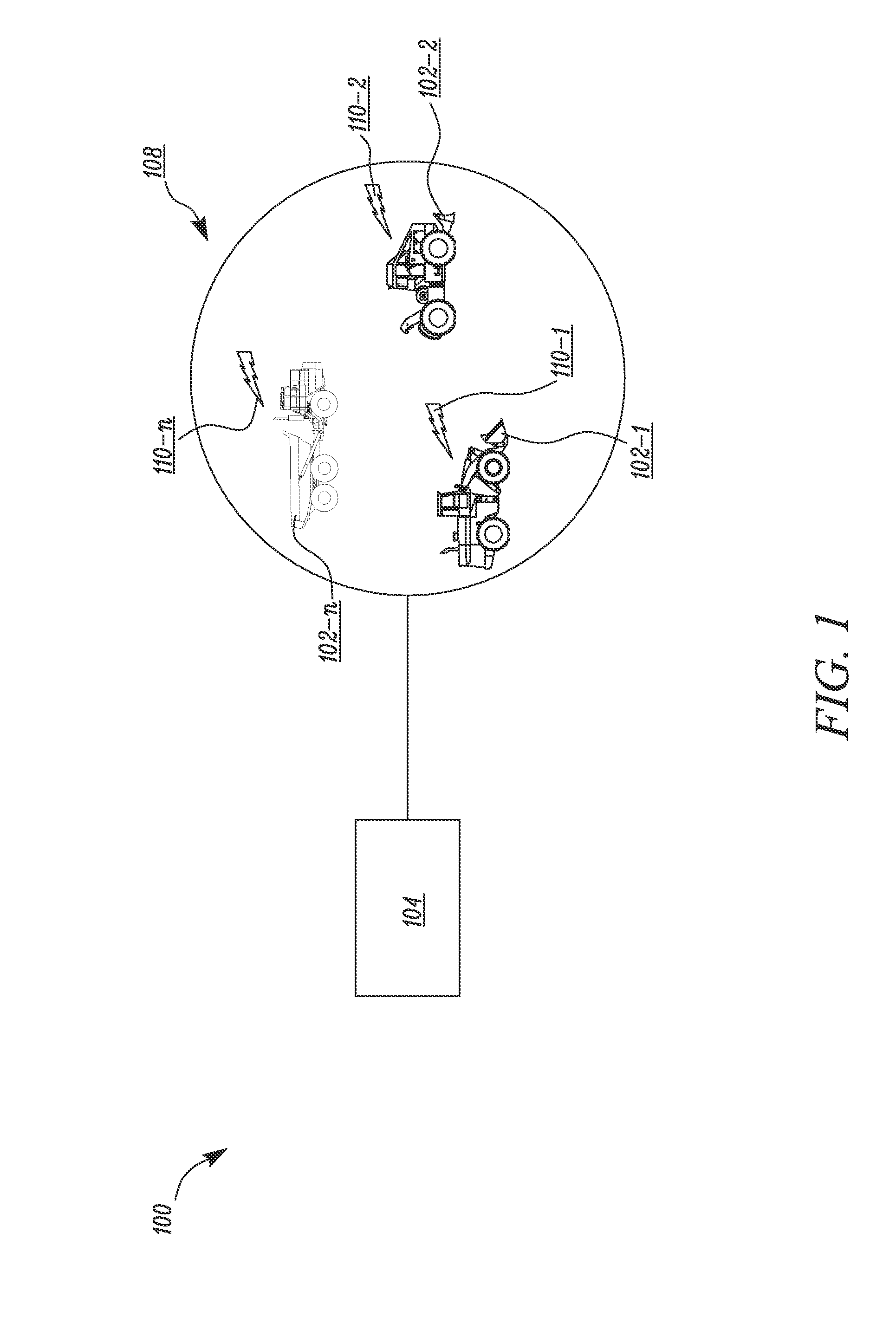
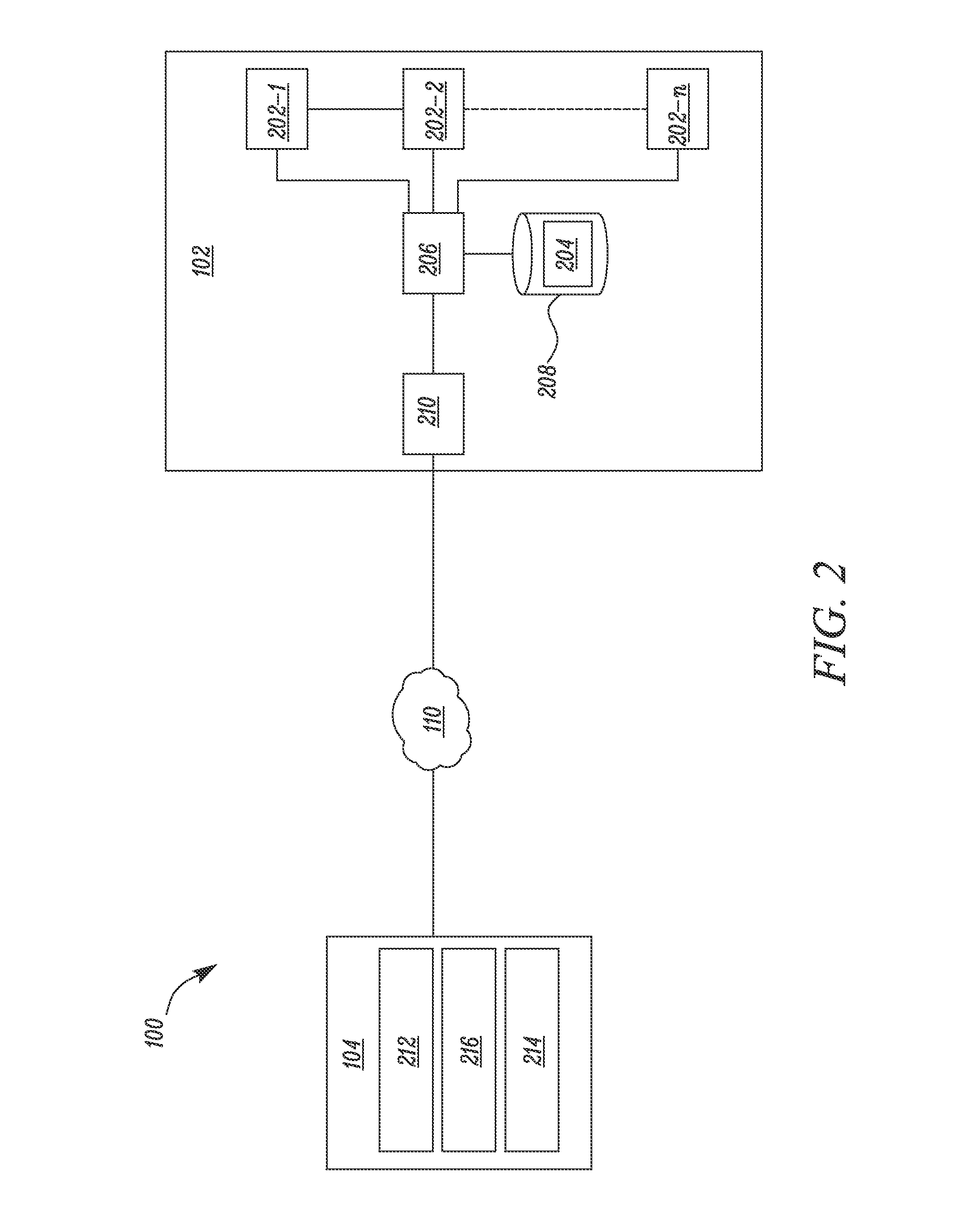
[0014]The present disclosure relates to a system and a corresponding method for remotely monitoring a plurality of machines. The detailed description of exemplary embodiments in the disclosure herein makes reference to the accompanying drawings and figures, which show the exemplary embodiments by way of illustration only. While these exemplary embodiments are described in sufficient detail to enable those skilled in the art to practice the disclosure, it should be understood that other embodiments may be realized and that logical and mechanical changes may be made without departing from the spirit and scope of the disclosure. It will be apparent to a person skilled in the pertinent art that this system can also be employed in a variety of other applications. Thus, the detailed description herein is presented for purposes of illustration only and not of limitation. For example, the steps recited in any of the method or process descriptions may be executed in any order and are not lim...


PUM


Abstract

A method for remotely monitoring one or more machines is disclosed. One or more machines available for communicating with a portable device over a wireless network are detected using the portable device. Fault data associated with each of the one or more machines is received. The fault data includes severity data indicative of a severity level associated with the fault data. Further, a list of the one or more machines is displayed on a display of the portable device based on the severity data.

Description

TECHNICAL FIELD[0001]The present disclosure relates to a system and method for remotely monitoring machines.BACKGROUND[0002]Multiple number and types of machines operate within a worksite. All of these machines may encounter one or more faults and failures associated with them. Some of these failures may not be very critical for the machine's performance, whereas some faults may be highly critical for the machine's performance. Such high critical failures may need immediate attention by an operator and / or service personnel in order to rectify the fault and / or replace a component within the machine which has failed.[0003]Generally, these faults in the machine may be monitored periodically by physically connecting the machine to a laptop or a computer and downloading the on-board information. However, physically connecting every machine in the worksite may be a time consuming and tedious task. Also, the service personnel may not know which machine has high criticality failures and whi...

Claims


Application Information

Patent Timeline
Patent Type & Authority Applications(United States)
IPC IPC(8): H04L12/26
CPCH04L43/0823E02F9/205E02F9/2054E02F9/267H04L67/12H04L67/125H04Q9/00H04Q2209/40H04W4/40H04M1/72415
Inventor GUNDLAPALLI, SAI PRAVEENAYYAMPERUMAL, PREETHICHALLA, RAMAKRISHNA V.BALASUBRAMANIAN, KRITHIKA
Owner CATERPILLAR GLOBAL MINING LLC
Learn More