Vehicle speed control device and vehicle equipped with vehicle speed control device

a technology of vehicle speed control and control device, which is applied in mechanical equipment, transportation and packaging, brake systems, etc., can solve the problems of not preventing the rotation of the rotary shaft, and achieve the effect of easy chang

Active Publication Date: 2014-08-14
NABLESCO CORP +1
View PDF8 Cites 35 Cited by
  • Summary
  • Abstract
  • Description
  • Claims
  • Application Information

AI Technical Summary

Benefits of technology

[0041]According to the present invention, a vehicle speed control device with respect to which the speed at which a centrifugal brake operat...

Problems solved by technology

Since the pair of locking pieces are pulled by each other with the spring, they do not preve...

Method used


Image

  • Vehicle speed control device and vehicle equipped with vehicle speed control device
  • Vehicle speed control device and vehicle equipped with vehicle speed control device
  • Vehicle speed control device and vehicle equipped with vehicle speed control device

Examples


first embodiment

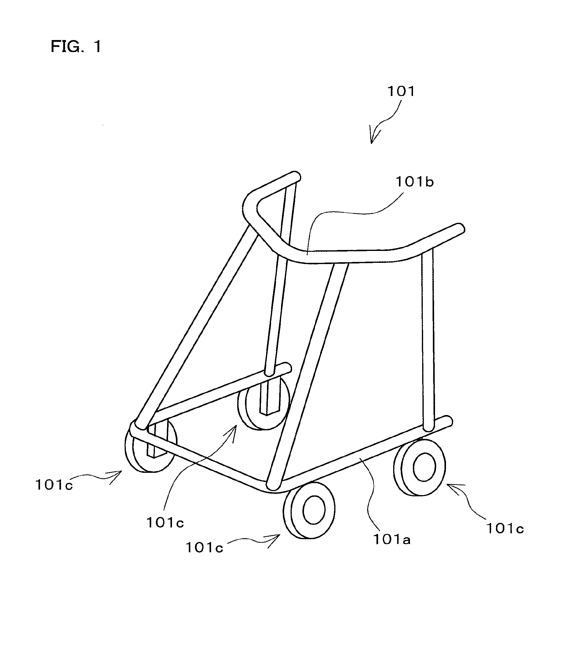
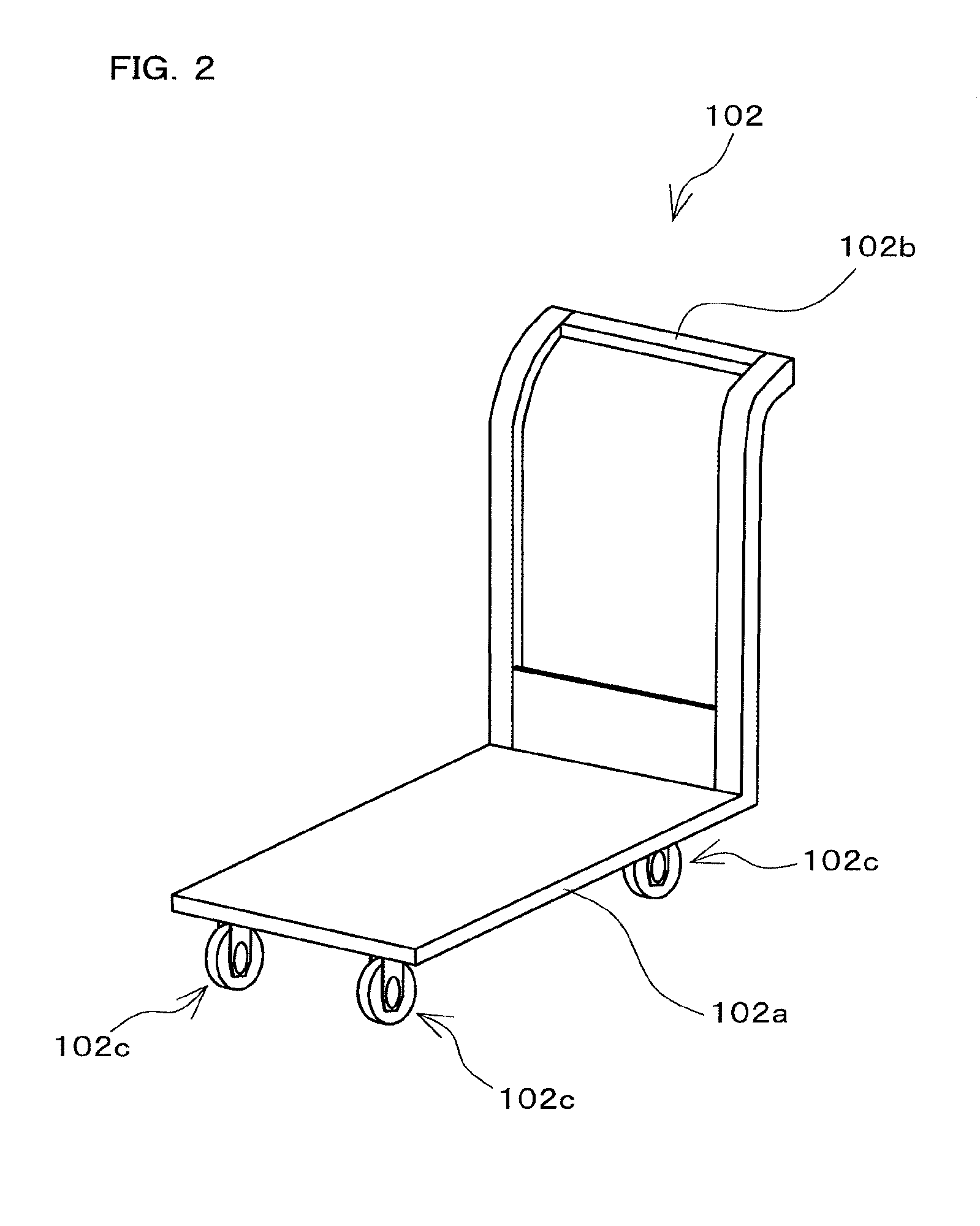
[0072]FIGS. 3 and 4 are exploded perspective views showing a wheel 101c and a part of a vehicle speed control device 1 (hereinafter also referred to simply as the “speed control device 1”) according to a first embodiment of the present invention. FIG. 5 is an exploded perspective view showing an enlargement of a part of the vehicle speed control device shown in FIG. 4. FIG. 6 is a diagram showing the speed control device 1 and the wheel 101c. FIG. 7 is a cross-sectional view of the speed control device 1 as viewed from the position of arrow A in FIG. 6. FIG. 8 is a partial cross-sectional view of the speed control device 1 as viewed from the position of arrow B in FIG. 6. FIG. 9 is a partial cross-sectional view of the speed control device 1 as viewed from the position of arrow C in FIG. 6.

[0073]Note that the exploded perspective views of the speed control device 1 and the wheel 101c are divided between FIGS. 3 and 4. The constituent elements shown in FIG. 3 are installed on the ins...

second embodiment

[0139]Next, a second embodiment of the present invention will be described. FIGS. 13A and 13B are diagrams schematically showing an internal structure of a vehicle speed control device 2 (hereinafter also referred to simply as a “speed control device 2”) according to the second embodiment of the present invention, and show a centrifugal brake unit 13a from the outside in the vehicle width direction. FIGS. 13A and 13B show the centrifugal brake unit 13a in different operational states.

[0140]The speed control device 2 is configured substantially similarly to the speed control device 1 in the first embodiment, and the centrifugal brake unit 13a is also configured substantially similarly to the centrifugal brake unit 13 in the first embodiment. However, the speed control device 2 is different from the speed control device in the first embodiment in the configuration of a position change mechanism 47 and a transmission mechanism 48 in the centrifugal brake unit 13a. The difference from t...

third embodiment

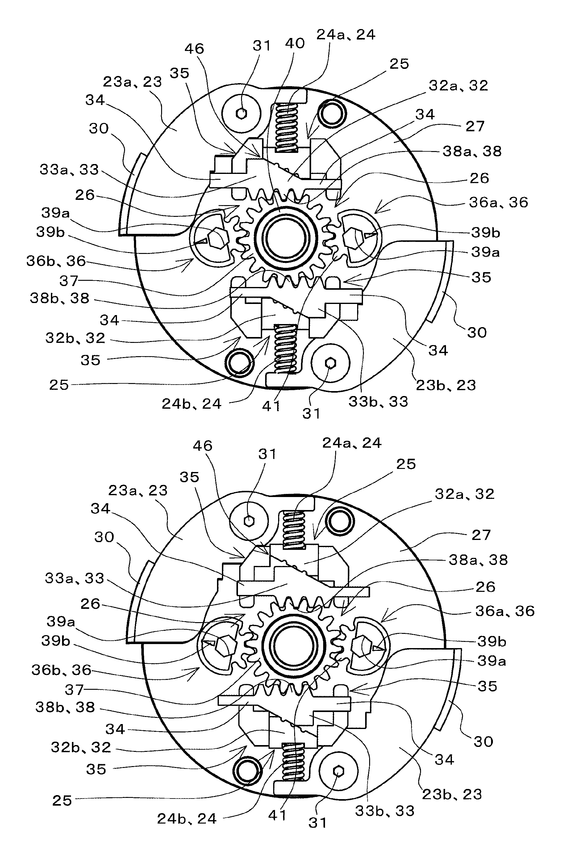
[0164]Next, a third embodiment of the present invention will be described. FIGS. 16A and 16B are diagrams schematically showing an internal structure of a vehicle speed control device 3 (hereinafter also referred to simply as a “speed control device 3”) according to the third embodiment of the present invention, and show a centrifugal brake unit 13b from the outside in the vehicle width direction. FIGS. 16A and 16B show the centrifugal brake unit 13b in different operational states.

[0165]The speed control device 3 is configured substantially similarly to the speed control device 1 in the first embodiment, and the centrifugal brake unit 13b is also configured substantially similarly to the centrifugal brake unit 13 in the first embodiment. However, the speed control device 3 is different from the speed control device in the first embodiment in the configuration of a position change mechanism 59 and a transmission mechanism 60 in the centrifugal brake unit 13b. Meanwhile, the position...


PUM


Abstract

Provided is a vehicle speed control device with respect to which the speed at which a centrifugal brake operates can be easily changed from the outside without disassembling the device. A brake drum 11 is fixed to a vehicle body 101a. A brake shoe 23 rotates around a rotary shaft 20 of the wheel 101c, and reduces the rotation speed of the wheel 101c as a result of coming into contact with an inner circumferential side face of the brake drum 11. A spring 24 prevents contact between the brake drum 11 and the brake shoe 23 when the rotation speed of the wheel 101c is lower than or equal to a predetermined speed, and permits contact between the brake drum 11 and the brake shoe 23 when the rotation speed of the wheel 101c exceeds the predetermined speed. A position change mechanism 25 is installed within the brake drum 11, and changes the position of an end of the spring 24 on one end side. A transmission mechanism 26 transmits a force that is input by an external operation to the position change mechanism 25 and drives the position change mechanism.

Description

TECHNICAL FIELD[0001]The present invention relates to a vehicle speed control device that is provided in a vehicle whose vehicle body moves due to a wheel rotatably attached to the vehicle body rotating as a result of a person manually pushing the vehicle body and that is capable of controlling the vehicle speed, and to a vehicle equipped with this speed control device.BACKGROUND ART[0002]Conventionally, vehicle speed control devices are known that are provided in a vehicle whose vehicle body moves due to a wheel rotatably attached to the vehicle body rotating as a result of a person manually pushing the vehicle body, and that are capable of controlling the vehicle speed (e.g., see Patent Documents 1 and 2). Patent Documents 1 and 2 disclose speed control devices that are provided in a vehicle configured as a walking supporter or a walking assistance vehicle.[0003]The speed control device disclosed in Patent Document 1 includes a governor brake mechanism section provided within a br...

Claims


Application Information

Patent Timeline
IPC IPC(8): B60T1/06B60T8/32B62B5/04
CPCB60T1/067B60T8/32B62B5/048B62B5/0404B60T7/126F16D59/00F16D51/20F16D2121/14F16D2125/64F16D2127/002F16D2127/008B60T8/86A61H2003/046A61H3/04
Inventor TAKEZAWA, YOSHINORIMATSUO, SHINPEITANIGUCHI, NAOYAKATSUMOTO, SATOSHI
Owner NABLESCO CORP
Why Eureka
Try Eureka