
Musical instrument location transmitting device and method of making

a technology of a transmitting device and a musical instrument, applied in the field of musical instruments, can solve the problems of destroying the purpose of stealing the musical instrument in the first instance, rendering the musical instrument useless and/or valueless, and reducing the energy requirements of operation

Active Publication Date: 2014-08-14
SCHAAL MICHAEL JOHN
View PDF2 Cites 0 Cited by
  • Summary
  • Abstract
  • Description
  • Claims
  • Application Information

AI Technical Summary

Benefits of technology

The patent text describes a way to prevent theft of musical instruments by attaching a location transmitting device to the instrument. This device can communicate with external devices like mobile phones or computers to quickly locate the instrument if it is stolen or lost. The location transmitting device is powered by a battery and is designed to conserve energy by intermittently outputting a signal when the instrument is moved. This way, the instrument can be quickly recovered and the thief may be caught. The method also includes the option to install a power supply line and port for an external power source to recharge the battery. This allows for longer periods of use without needing to recharge the battery. Overall, the patent is about a way to make musical instruments safer and easier to recover if they are stolen or lost.

Problems solved by technology

In the event a would-be thief is aware of the existence of a location transmitting device permanently installed in a musical instrument (such as by an insignia on the outside of the guitar), the thief may be required to permanently destroy the musical instrument in the process of removing the location transmitting device in order to steal the instrument, which thereby renders the musical instrument useless and / or valueless because it would not be playable or resalable.
This would defeat the purpose of stealing the musical instrument in the first instance.

Method used


Image

  • Musical instrument location transmitting device and method of making
  • Musical instrument location transmitting device and method of making
  • Musical instrument location transmitting device and method of making

Examples


Embodiment Construction

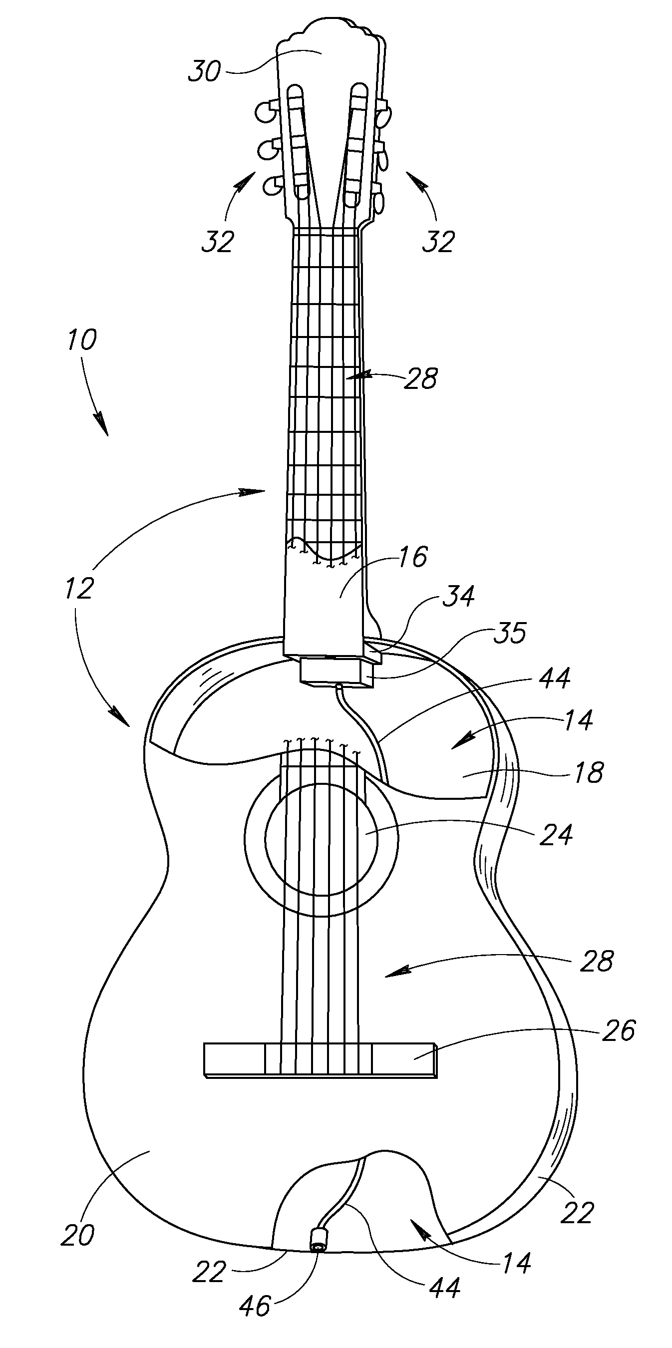
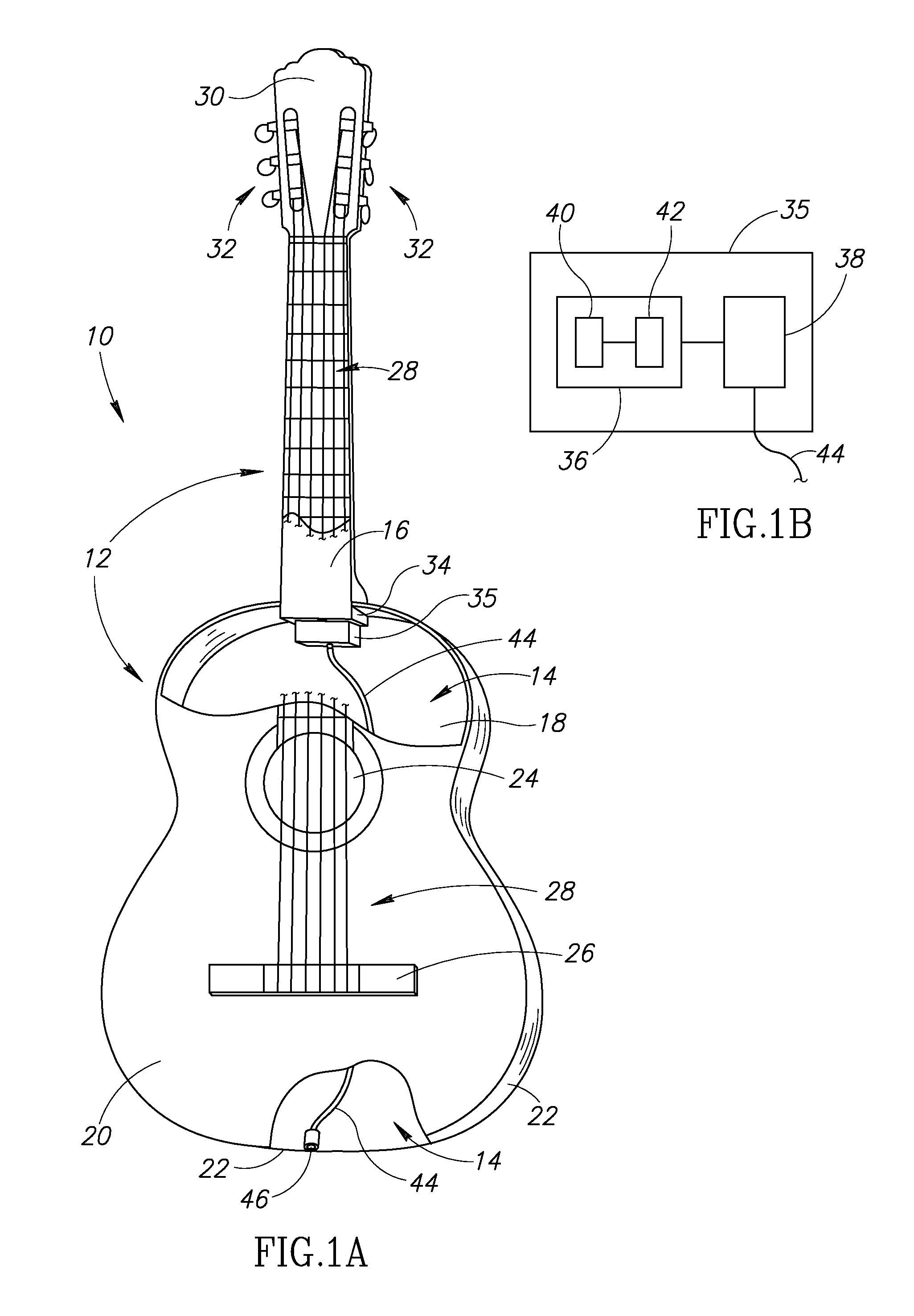
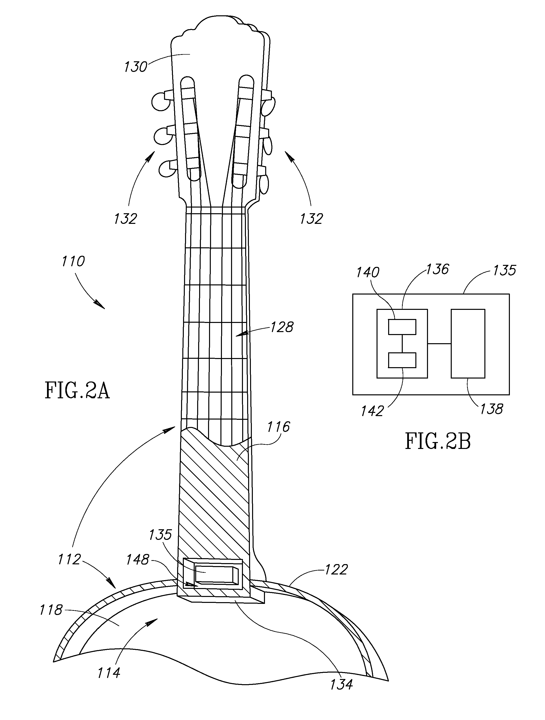
[0028]FIG. 1A shows a musical instrument 10 according to one aspect of the present disclosure. In this example, the musical instrument is an acoustic guitar 10. The guitar 10 includes a plurality of musical components, such as a body 12 having a cavity 14, a neck 16, a bottom 18, a top 20, sides 22, a sound hole 24, a bridge 26, strings 28, a head 30, tuning keys 32, and a neck block 34 extending partially into the cavity 14. As shown in the cutaway of the guitar 10, a transmitter housing 35 is permanently secured inside the body 12 of the guitar 10. FIG. 1B shows one example of a transmitter housing 35 having a location transmitting device 36 and an electric power source 38 electrically coupled to each other. The location transmitting device 36 may include a location sensing unit 40 and a wireless transmitter 42 electrically coupled to each other. In this example, the transmitter housing 35 is permanently secured to the neck block 34 inside the cavity 14 of the body 12. It will be ...


PUM


Abstract

A musical instrument location transmitting device and system includes a musical instrument having a location transmitting device and an electric power source permanently secured in the musical instrument in a position that requires removal of a musical component of the musical instrument in order to remove the location transmitting device. The location transmitting device includes a location sensing unit and a wireless transmitter that outputs a location of the musical instrument. A system wirelessly monitors a location of the musical instruments. A method of making a musical instrument includes coupling a location transmitting device inside a musical instrument and closing the musical instrument to permanently install the location transmitting device.

Description

BACKGROUND[0001]1. Technical Field[0002]The present disclosure pertains to musical instruments, and more particularly, to musical instruments having devices to monitor and locate the musical instruments.[0003]2. Description of the Related Art[0004]Every year over 1 million instruments are stolen from musicians and less than 3% are recovered. Even though many stolen musical instruments are unique and identifiable by some aspects, nearly all are unrecovered by the true owners. This is partially because of the ease of concealing and transporting certain musical instruments, such as guitars, violins, and the like. Furthermore, many musical instruments are very valuable, making them more prone to theft than less expensive and less available merchandise. Some collectible guitars have been sold for millions of dollars. For example, “The Strat” generated a total of 3.7 million dollars at auction. As another example, some violins have been sold for millions of dollars. The “Vieuxtemps Guarne...

Claims


Application Information

Patent Timeline
IPC IPC(8): G01S1/04G10G7/00
CPCG01S1/042G10G7/00G10D3/00G01S5/0226G10D1/08G01S19/16G08B13/1427G08B21/0227G08B21/023G08B21/0288
Inventor SCHAAL, MICHAEL JOHN
Owner SCHAAL MICHAEL JOHN
Learn More