
Sailing windmill, fully responsive vawt

a windmill and fully responsive technology, applied in the direction of machines/engines, renewable energy generation, greenhouse gas reduction, etc., can solve the problems of inability to restore the aftermath, design is impractical, and design is over-complicated

Inactive Publication Date: 2014-08-14
XIA ZHONG AI
View PDF2 Cites 5 Cited by
  • Summary
  • Abstract
  • Description
  • Claims
  • Application Information

AI Technical Summary

Benefits of technology

The patent text means to work on three-fourths of the central axis on windy days and avoid negative impacts on rest. Basically, the goal is to make the most out of the favorable weather and minimize the negative effects on the overall performance.

Problems solved by technology

It is very hard to operate simultaneously without interfering the spinning of the vanes, it has to be shutdown manually on excessive wind, and also not easy to restore aftermath.C_U.S. Pat. No. 4,496,283 A_January 1985, Andrej A. KodricDiscussion: The design is impractical; the position and angle of control means is not correct; the device at best could work only half of each rotation effectively.D_U.S. Pat. No. 1,794,930 A_March 1931, Charles H SpencerDiscussion: The design was over-complicated, not feasible and at best the device could only work half of each turn.E_U.S. Pat. No. 3,897,170 A_July 1975, Arthur DarvishianDiscussion: The design was different and not feasibleF_U.S. Pat. No. 485,933 A_November 1892, David C. HermanDiscussion: The angle of the working members' movement is pertinent but by no possible means to deal with excessive wind since all the working members are restrained within two rings and stop rods therefore the whole device is set to rotate in whatsoever condition of wind until being destroyed by immoderate wind.

Method used


Image

  • Sailing windmill, fully responsive vawt
  • Sailing windmill, fully responsive vawt
  • Sailing windmill, fully responsive vawt

Examples


Embodiment Construction

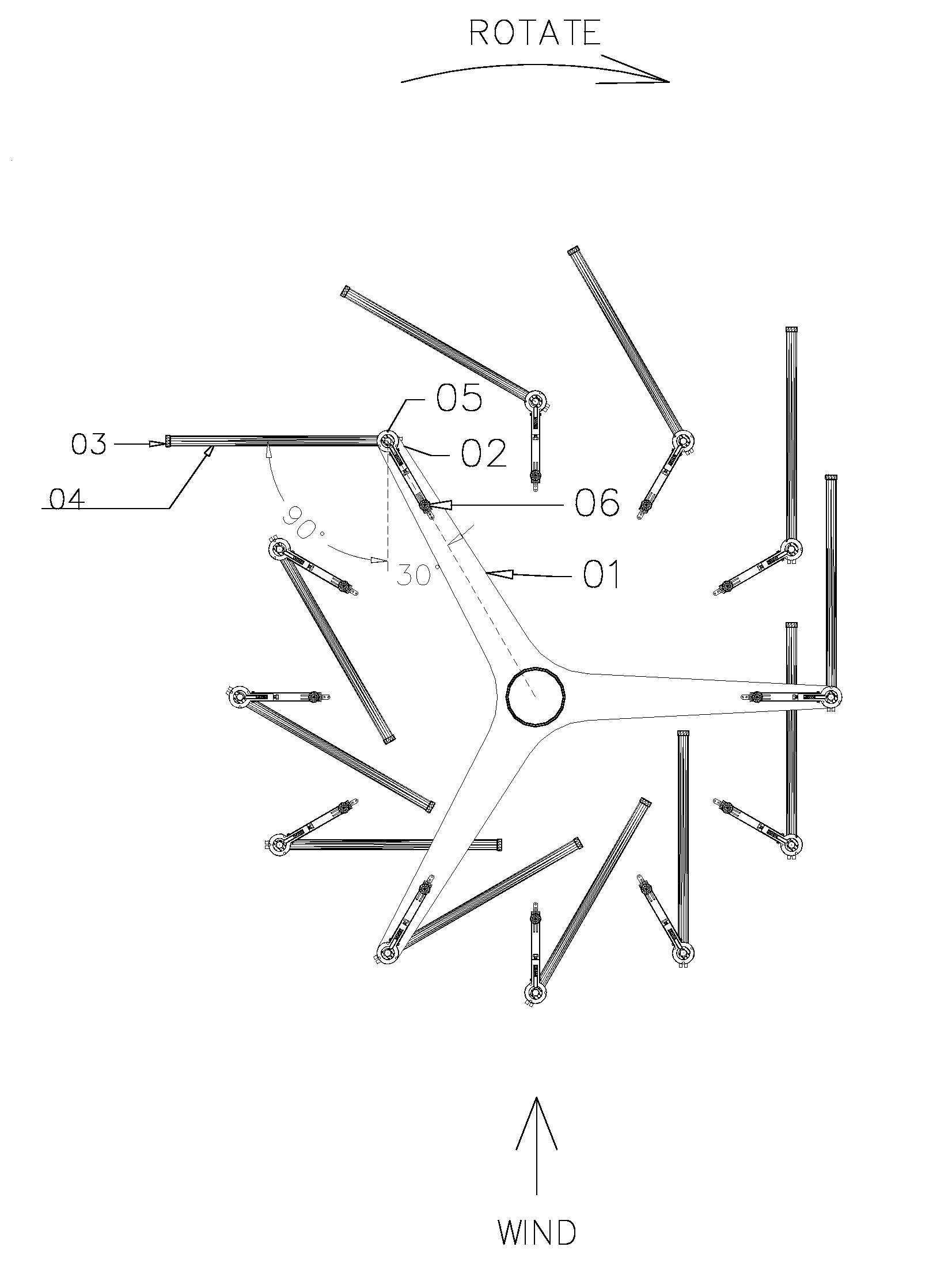
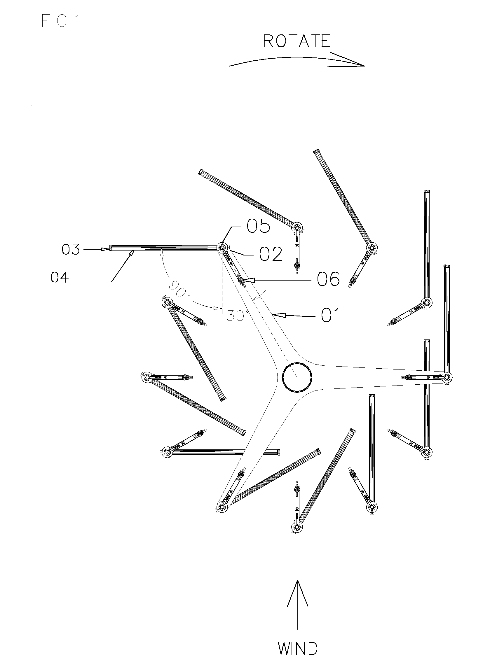
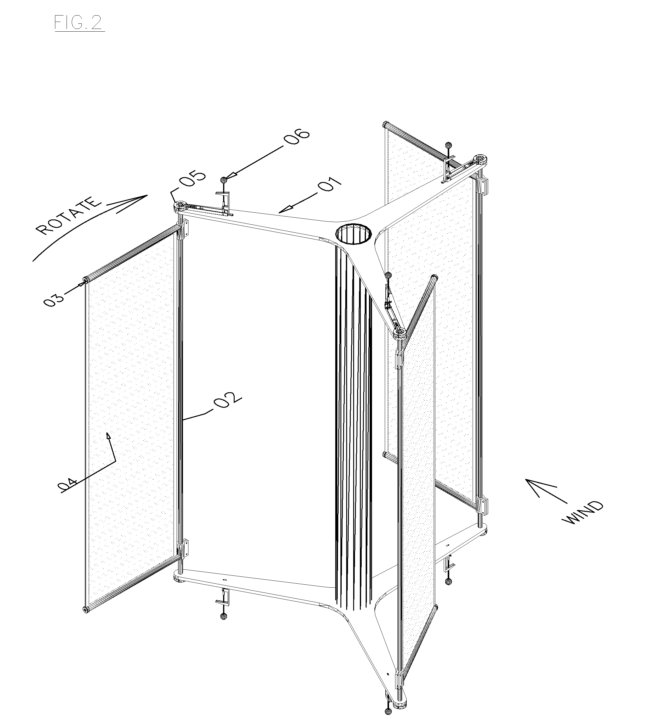
[0035]The present Invention relates to a windmill comprising plural working members pivotally attached to a rotor structure 01 to rotate around a vertical central axis.

[0036]The said rotor structure 01 includes upper and lower arms along with a central shaft and bearings.[0037]On each far end of said upper and lower arms bored holes or cavities to contain bearings etc. for working members.

[0038]Each working member incorporates:[0039]Elbow shaft or satellite shaft 02 with bearings (not shown) installed on both ends.[0040]A pair of forearms 03 is attached on the said elbow shaft, holding and turning with the working part 04.[0041]The working part 04 is equivalent to a square sail, a vane, a blade or a wing, suggesting a piece of sail cloth with 2 rods on both upper and lower ends to insert into the slots of said forearms 03 for easy installation.[0042]At least one end of each elbow shaft 02 furnished a special hinge bearing 05, functioning as a releasable bumper stop to control whethe...


PUM


Abstract

The present invention relates to a vertical axis windmill. The windmill rotates on an upright post, with plural arms holding articulated working members circling around. Each working member has a pivotal edge like a vane, a flag or a hinged door, swings on its own axis and also circles around the axis of the central post. On the axis of each working member furnished a special hinge bearing to control and restrain the movement of each, flipping and engaging the favorable wind in about ¾ turn of the central axis but disengaging in the rest ¼ turn. The said hinge bearing also provides elastic releasable means, along with a centrifugal governor, to deal with excessive wind, allowing the working member to disengage to a temporary idle position as a free weather vane.

Description

BACKGROUND OF THE INVENTION[0001]As the inventor noticed that a modern HAWT <Horizontal Axis Wind Turbine with airfoil> stops working on low speed wind, while some sailing boats are still sailing around nearby. That means the boat sail is more efficient to capture the wind.[0002]The efficiency of HAWT, ideally, can be 59.3 percent, in reality, maybe somewhere around 35 percent.[0003]The drawback of a HAWT is that: it is not good at dealing with frequent changes of variable wind conditions; it needs to orientate the direction of the wind; it is very expensive for manufacture, installation and maintenance. Also, it kills birds by accident, about 400,000 a year by some estimates.[0004]VAWT, a vertical axis wind turbine, is more visually appealing, and in theory, should have some advantages over HAWT. But so far both two major VAWT designs have the same drawback: Efficiency. The Savonius rotor's efficiency range 5 to 10 percent, as for Darrieus model with airfoil design VAWT, mayb...

Claims


Application Information

Patent Timeline
Patent Type & Authority Applications(United States)
IPC IPC(8): F03D1/06
CPCF03D1/0633F03D3/067Y02E10/74Y02E10/72
Inventor XIA, ZHONG AI
Owner XIA ZHONG AI
Learn More