

Method and apparatus for connection between client and server
a server and client technology, applied in the direction of substation remote connection/disconnection, instruments, digital computers, etc., can solve the problems that the user of a smart phone currently cannot safely manipulate the smart phone while operating a vehicle, and the number of electric and electronic equipment applied to vehicles has increased, so as to achieve the effect of safe manipulation of a mobile phon
- Summary
- Abstract
- Description
- Claims
- Application Information
AI Technical Summary
Benefits of technology
Problems solved by technology
Method used
Image

Examples
first embodiment
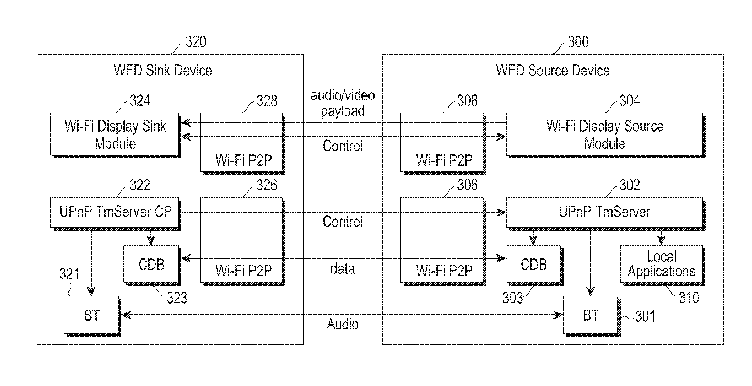
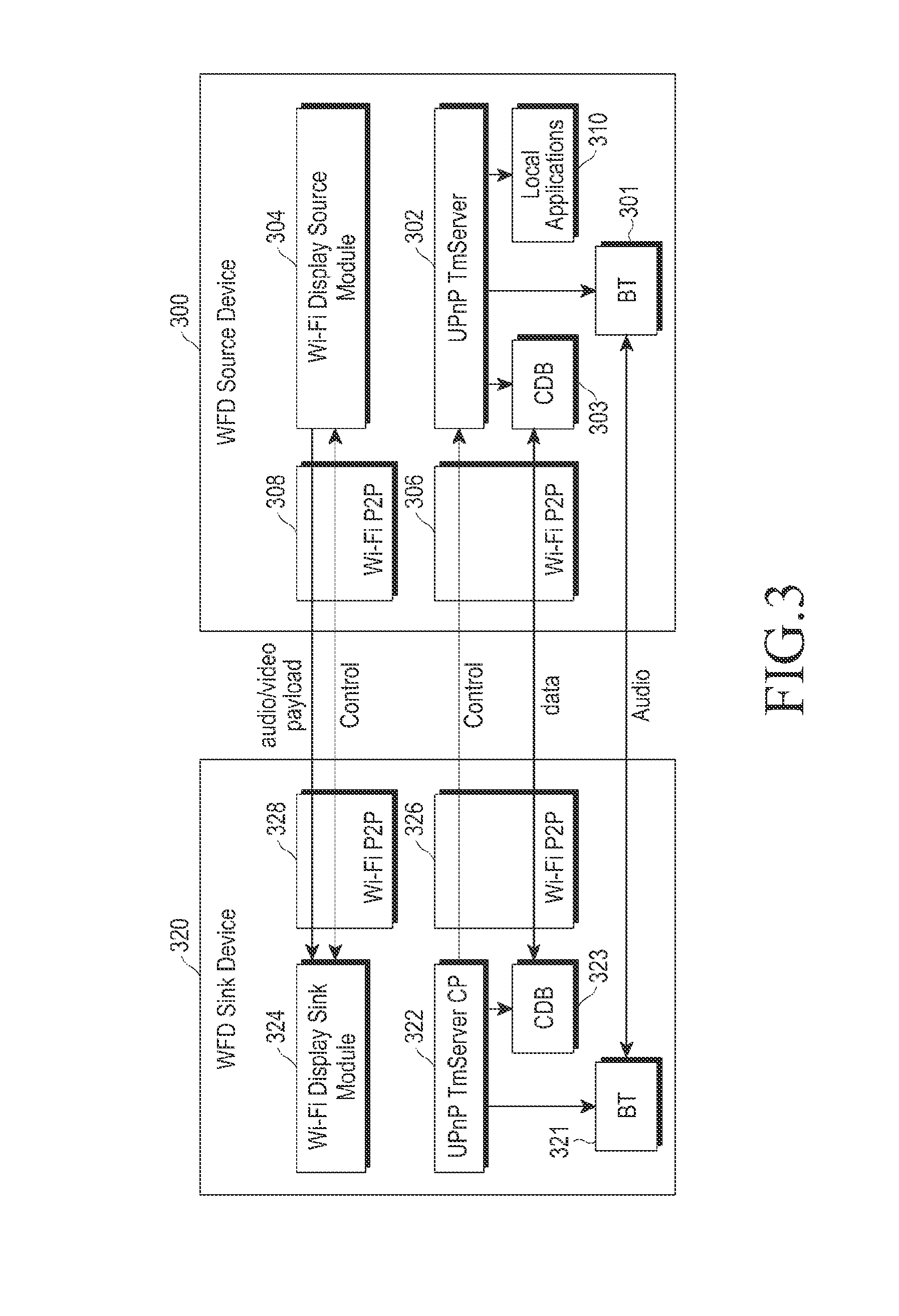
[0041]FIG. 3 illustrates a WFD structure according to the present invention.
[0042]Although a WFD Sink Device 320 and a WFD Source Device 300 are illustrated in FIG. 3 by example, these devices may be replaced by a Mirrolink Client and Mirrorlink Server, for example.
[0043]A UPnP TmServer CP 322 may exist inside the WFD Sink Device 320, and may exist separately from a Wi-Fi Display Sink Module 324. The UPnP TmServer CP 322 may discover and control a UPnP TmServer 302 in the WFD Source Device 300, using a Wi-Fi P2P Connection which is separate from that of the Wi-Fi Display Sink Module 324. The Wi-Fi Display Sink Module 324 and WFD Display Source Module 304 may use a Wi-Fi P2P Connection 328 and a Wi-Fi P2P Connection 308, respectively, and the UPnP TmServer CP 322 and the UPnP TmServer 302 may use a Wi-Fi P2P Connection 326 and a Wi-Fi P2P Connection 306, respectively.
[0044]The WFD modules (e.g., the Wi-Fi Display Sink Module 324 and the WFD Display Source Module 304) and the UPnP mod...
second embodiment
[0055]FIG. 5 illustrates a WFD structure according to the present invention.
[0056]As in the first embodiment of the present invention, a UPnP TmServer CP 522 may exist in a WFD Sink Device 520, and may exist separately from Wi-Fi Display Sink Module 524.
[0057]However, the UPnP TmServer CP 522 may discover a UPnP TmServer 502 in a WFD Source Device 500 using an RTSP message exchanged between the Wi-Fi Display Sink Module 524 and a Wi-Fi Display Source Module 504, by using a Wi-Fi P2P Connection which is the same as that of the Wi-Fi Display Sink Module 524.
[0058]The process after the discovery is the same as that of the normal UPnP scheme. If a part of the UPnP process is replaced using RTSP in this manner, the following advantages are realized.
[0059]The Addressing and Discovery processes defined in UPnP Device Architecture (DA) may be omitted. The UPnP process 420 that is separately performed in UPnP is the process that has been performed in the WFD process 410. Therefore, by replac...
third embodiment
[0103]FIG. 8 illustrates a WFD setup process according to the present invention.
[0104]The third embodiment of the present invention is similar to the second embodiment of the present invention, except that the information exchanged in step 613 may be sent through a payload of Sub Element (with ID=11) in an IE in step 801.
[0105]As in the second embodiment of the present invention, in addition to the presented information, the Device information which is not provided in the existing WFD Device Discover, Service Discovery, and Capability Negotiation processes may be exchanged between WFD Devices based on the WFD IE information in the third embodiment of the present invention.
PUM
 Abstract
Description
Claims
Application Information