Parking lock device

Active Publication Date: 2014-08-21
TOYOTA JIDOSHA KK
View PDF3 Cites 20 Cited by
  • Summary
  • Abstract
  • Description
  • Claims
  • Application Information

AI Technical Summary

Benefits of technology

[0009]The invention provides a parking lock device that prevents noise from being produced due to a contact between a gear and a lock.
[0010]An aspect of the invention relates to a parking lock device that is installed in a case of a transmission of a vehicle. The parking lock device includes a gear, a lock, a receiver, a cam, and a damper. The gear includes a plurality of teeth arranged in a circumferential direction of the gear. A tooth space is defined between the plurality of teeth. The lock includes a pawl to be engaged in the tooth space. The lock is moveable between an engagement position and a retreat position. In the engagement position, the pawl

Problems solved by technology

There is a backlash betwe

Method used


Image

  • Parking lock device
  • Parking lock device
  • Parking lock device

Examples


Embodiment Construction

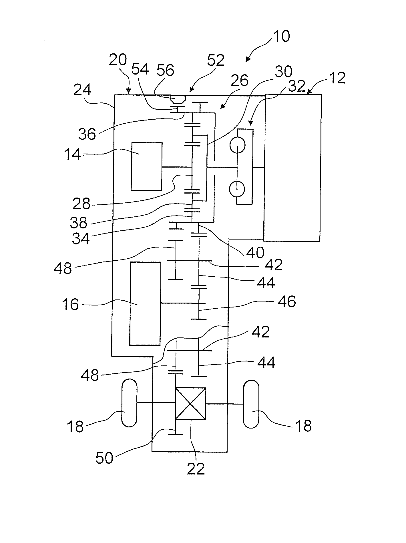
[0028]The embodiments of the invention will be described hereinafter with reference to the drawings. FIG. 1 is a skeleton view showing the overall configuration of a power unit 10 of a vehicle according to the present embodiments of the invention. The power unit 10 has an internal combustion engine 12 and two electric motors 14 and 16 as prime movers that drive the vehicle. The internal combustion engine 12 can be configured as a reciprocating piston engine such as an Otto engine, a diesel engine or the like. The two electric motors will be referred to as the first electric motor 14 and the second electric motor 16. The two electric motors function as electric generators as well. For example, the first electric motor 14 can generate electricity by being driven by the internal combustion engine 12. The second electric motor 16 can generate electricity by being driven by the inertia of the vehicle.

[0029]The power unit 10 has a transmission 20 that converts speeds of outputs of the pri...


PUM


Abstract

A parking lock device that is installed in a transmission of a vehicle includes a gear, a lock, a receiver, a cam, and a damper. The lock has a pawl that can be engaged in a tooth space between the teeth of the gear. The lock moves between an engagement position at which the pawl is engaged in the tooth space to lock the gear and a retreat position at which the pawl is not engaged in the tooth space. The receiver is arranged to be fixed to a case of the transmission. The cam moves forward and backward with respect to a gap between the receiver and the lock. The cam holds the lock at the engagement position when having entered the gap. The damper is provided in a vibration transmission path to dampen vibrations transmitted to the case of the transmission.

Description

INCORPORATION BY REFERENCE[0001]The disclosure of Japanese Patent Application No. 2013-029238 filed on Feb. 18, 2013 including the specification, drawings and abstract is incorporated herein by reference in its entirety.BACKGROUND OF THE INVENTION[0002]1. Field of the Invention[0003]The invention relates to a parking lock device that locks a shaft connecting to wheels to prevent a vehicle from moving when the vehicle is parked.[0004]2. Description of Related Art[0005]A parking lock device of a vehicle has a gear that is fixed to a shaft connecting to wheels, and a lock that is engaged in a tooth space of the gear to lock the gear. It should be noted herein that the shaft connecting to the wheels means a shaft that rotates while establishing a relationship of being constantly fixed to the wheels. The gear is locked to lock the wheels, thereby preventing the vehicle from moving when the vehicle is parked.[0006]The parking lock device is provided in a transmission of the vehicle. The t...

Claims


Application Information

Patent Timeline
IPC IPC(8): B60T1/00
CPCB60T1/005F16D63/006F16D2125/66F16H63/3425
Inventor ISOMURA, HARUOTAKEKAWA, HIROSHI
Owner TOYOTA JIDOSHA KK
Why Eureka
Try Eureka