Vehicle component

a technology of vehicle components and components, applied in mechanical equipment, rotary machine parts, transportation and packaging, etc., can solve the problem that the total weight of the positive connection strut is a considerable fraction, and achieve the effect of reducing the durability of the interlocking connection, and obtaining particularly inexpensively

Active Publication Date: 2014-08-21
ZF FRIEDRICHSHAFEN AG
View PDF6 Cites 9 Cited by
  • Summary
  • Abstract
  • Description
  • Claims
  • Application Information

AI Technical Summary

Benefits of technology

[0022]In the case of an interlocking connection of the ductile insert with the connection zone, it is advantageous for the weak-points to be outside the interlocking connection area, so that a deformation of the ductile insert has no, or only a slight negative effect on the durability of the interlocking connection. Preferably therefore, the weak-point is not located in the interlock area.
[0023]The circumferential contour of the ductile insert can be circular. Preferably however, the circumferential contour of the ductile insert deviates from a circular shape. In that way, due to the geometry of the insert alone the connection zones can be connected to one another with interlock in a rotationally fixed manner. For example the ductile insert can be formed by a closed or open hollow profile. Preferably, the ductile insert is formed by a U-section, which can be obtained particularly inexpensively.

Problems solved by technology

Yet, the metallic insert accounts for a considerable fraction of the total weight of the positive connection strut.

Method used


Image

  • Vehicle component
  • Vehicle component
  • Vehicle component

Examples


first embodiment

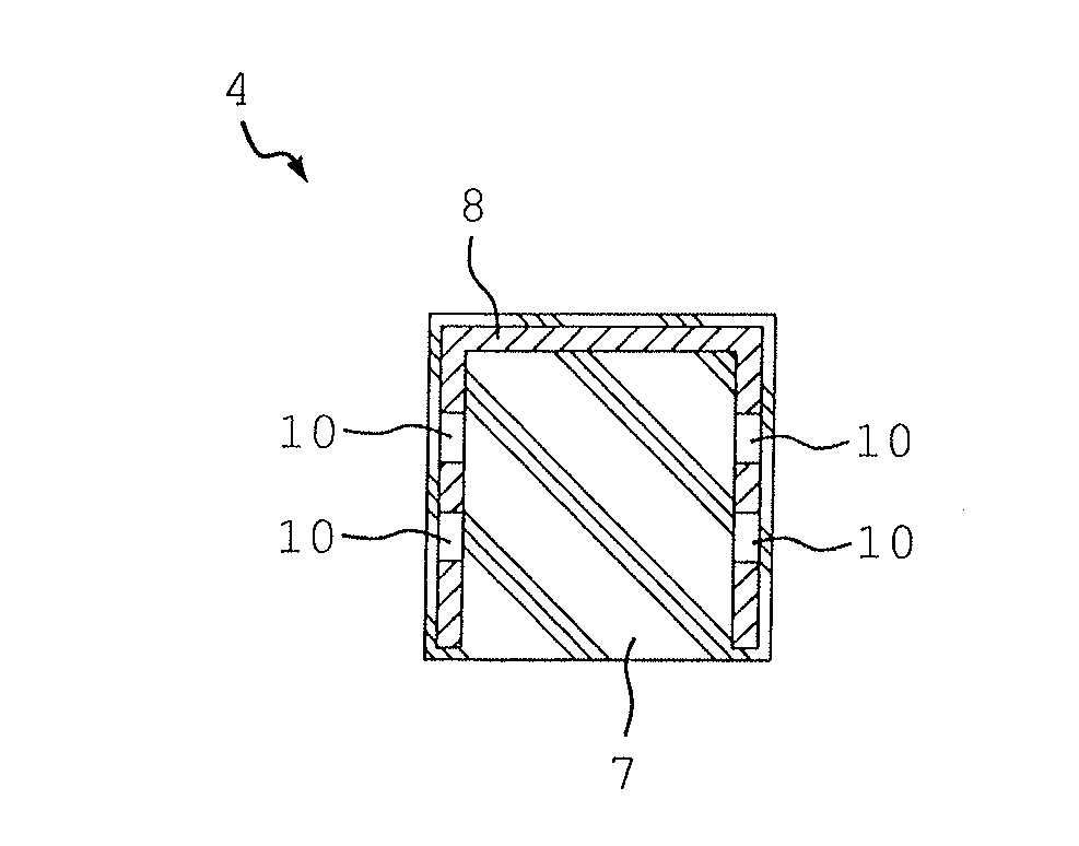
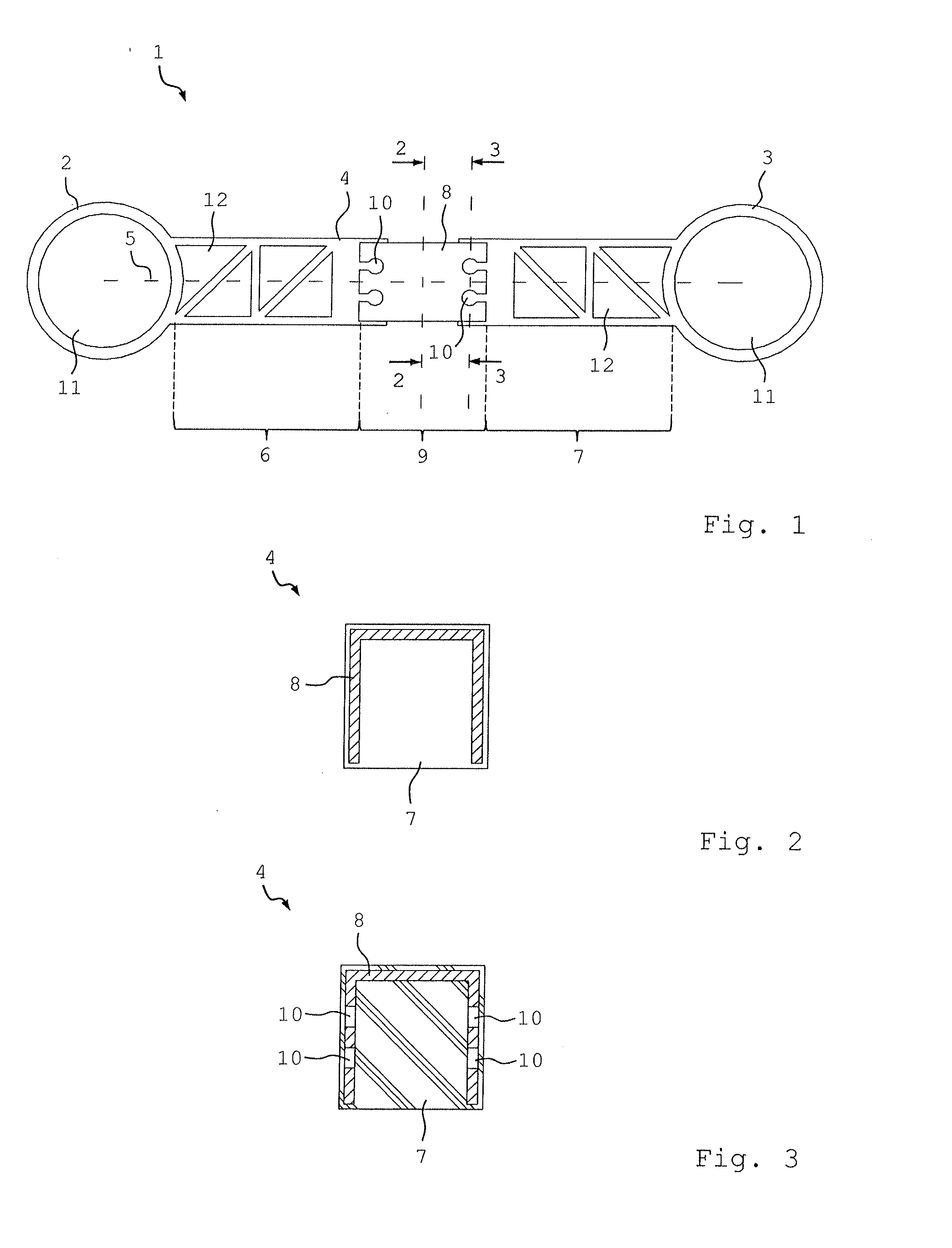
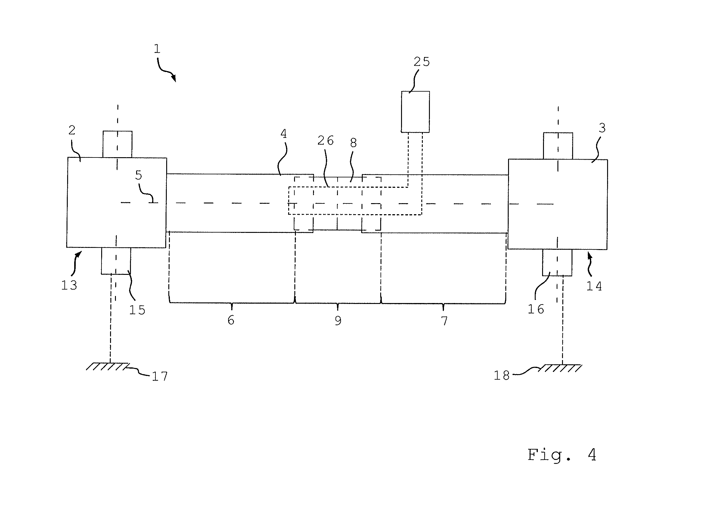
[0047]FIGS. 1 to 3 show different views of a chassis component 1 according to the invention, in which two connection points 2 and 3, each forming a joint holder, are connected rigidly to one another by means of a structural component 4 in the form of a strut. The structural component 4 of elongated form has a central longitudinal axis 5 and the structural component 4 is divided along its central longitudinal axis 5 into three zones. A connection zone 6 of the structural component 4 is formed in one piece with the connection point 2, which latter forms a free end of the connection zone 6. In addition a connection zone 7 of the structural component 4 is formed in one piece with the connection point 3, which latter forms a free end of the connection zone 7. Thus, the connection zones 6 and 7 form end areas of the structural component 4. A distance away from the connection points 2 and 3, the connection zones 6 and 7 are connected rigidly to one another by means of an insert 8, which de...

second embodiment

[0058]Each connection point 2, 3, 19 has a recess 11 in the form of a through-going hole of circular shape. Into each of these recesses 11 is inserted a joint, for example in the form of a ball joint or a rubber mounting, after which the chassis component 1 is fitted into the vehicle by means of the joints. In the second embodiment the recess 11 of the connection point 3 extends transversely to the recess 11 of the connection points 2 and 19.

[0059]FIGS. 6a-6i shows sections through the insert 8 taken along the section line 6-6 in FIG. 5, wherein nine different variants are shown for the ductile insert 8. Any of these variants can be chosen for the inserts 8 and 23. It is also possible to choose different variants for the inserts 8 and 23.

[0060]Variant of FIG. 6a shows a two-part design of the insert 8, whose parts are in each case connected by electric conductors 26 and 27 to a detection device 25. If the insert 8 is deformed the distance between the two parts changes, which results...


PUM


Abstract

A vehicle component with at least two connection points, a structural component that extends between the connection points and rigidly connects them with one another. The structural component comprises at least one insert made of a ductile material and at least two connection zones that support or form the two connection points, at least one of the zones comprises plastic. The structural component comprises at least one intermediate section that connects the two connection zones rigidly to one another and comprises the insert or is formed by the insert, this section is more ductile than at least one of the two connection zones and, in relation to a mechanical overload of the structural component, forms a locally delimited weak-point or region.

Description

[0001]This application is a National Stage completion of PCT / EP2012 / 054355 filed Mar. 13, 2012, which claims priority from German patent application serial no. 10 2011 007 390.6 filed Apr. 14, 2011.FIELD OF THE INVENTION[0002]The invention concerns a vehicle component having at least two connection points and a structural component that extends between the connection points and connects them rigidly to one another, which component comprises at least one insert made of a ductile material and at least two connection zones that support or form the connection points, at least one of the zones being made of plastic.BACKGROUND OF THE INVENTION[0003]DE 101 53 799 A1 discloses a positive-force connection strut of a chassis of a passenger vehicle or a utility vehicle for forming a connection between a chassis and a wheel carrier, which has an elongated basic body and at least two end-positioned bearing mountings for transmitting forces in and out, such that the basic body consists of at leas...

Claims


Application Information

Patent Timeline
Patent Type & Authority Applications(United States)
IPC IPC(8): B60G7/00
CPCB60G7/001B60G17/019B60G2204/1162B60G2206/016B60G2206/10B60G2206/71B60G2206/72B60G2400/60B60G2400/64B60G2600/04F16C7/06F16C2202/00F16C2326/05F16C7/02
Inventor GLEASON, JOHNADAMCZYK, DIRK
Owner ZF FRIEDRICHSHAFEN AG
Why Eureka
Try Eureka