Piezoelectric generator, sensor node, and method of manufacturing piezoelectric generator

a piezoelectric generator and sensor node technology, applied in the direction of generator/motor, piezoelectric/electrostrictive transducer, transducer type, etc., can solve the problems of difficult low-profiling and cost reduction, and achieve low cost, efficient generation of electricity, and enhanced freedom of installation

Inactive Publication Date: 2014-08-21
SEIKO EPSON CORP
View PDF0 Cites 0 Cited by
  • Summary
  • Abstract
  • Description
  • Claims
  • Application Information

AI Technical Summary

Benefits of technology

[0028]According to this configuration, since the piezoelectric generator, which efficiently generates electricity due to an external vibration, is provided as the power source, power source replacement of the sensor node can also be made unnecessary. Since the piezoelectric generator, which can be manufactured at low cost, functions as not only the power source but also the sensor, the low-price sensor node can be provided. Further, since the base body of the piezoelectric generator can be formed to have an arbitrary shape, the freedom of installation can be enhanced compared to the case in which the base body is formed of a silicon substrate or the like.

Problems solved by technology

However, the piezoelectric generator described in Document 1 has a configuration that the support member intervenes under the piezoelectric transducer, and the deformable section of the support member vibrates in accordance with the piezoelectric transducer, and therefore, there arises a problem that it is difficult to achieve low-profiling.
Since the manufacturing process of the piezoelectric generator requires an expensive vacuum (low-pressure) deposition device, and includes a complicated process using the photolithography process and the etching process, there arises a problem that cost reduction is difficult.

Method used


Image

  • Piezoelectric generator, sensor node, and method of manufacturing piezoelectric generator
  • Piezoelectric generator, sensor node, and method of manufacturing piezoelectric generator
  • Piezoelectric generator, sensor node, and method of manufacturing piezoelectric generator

Examples


first embodiment

Configuration of Piezoelectric Generator

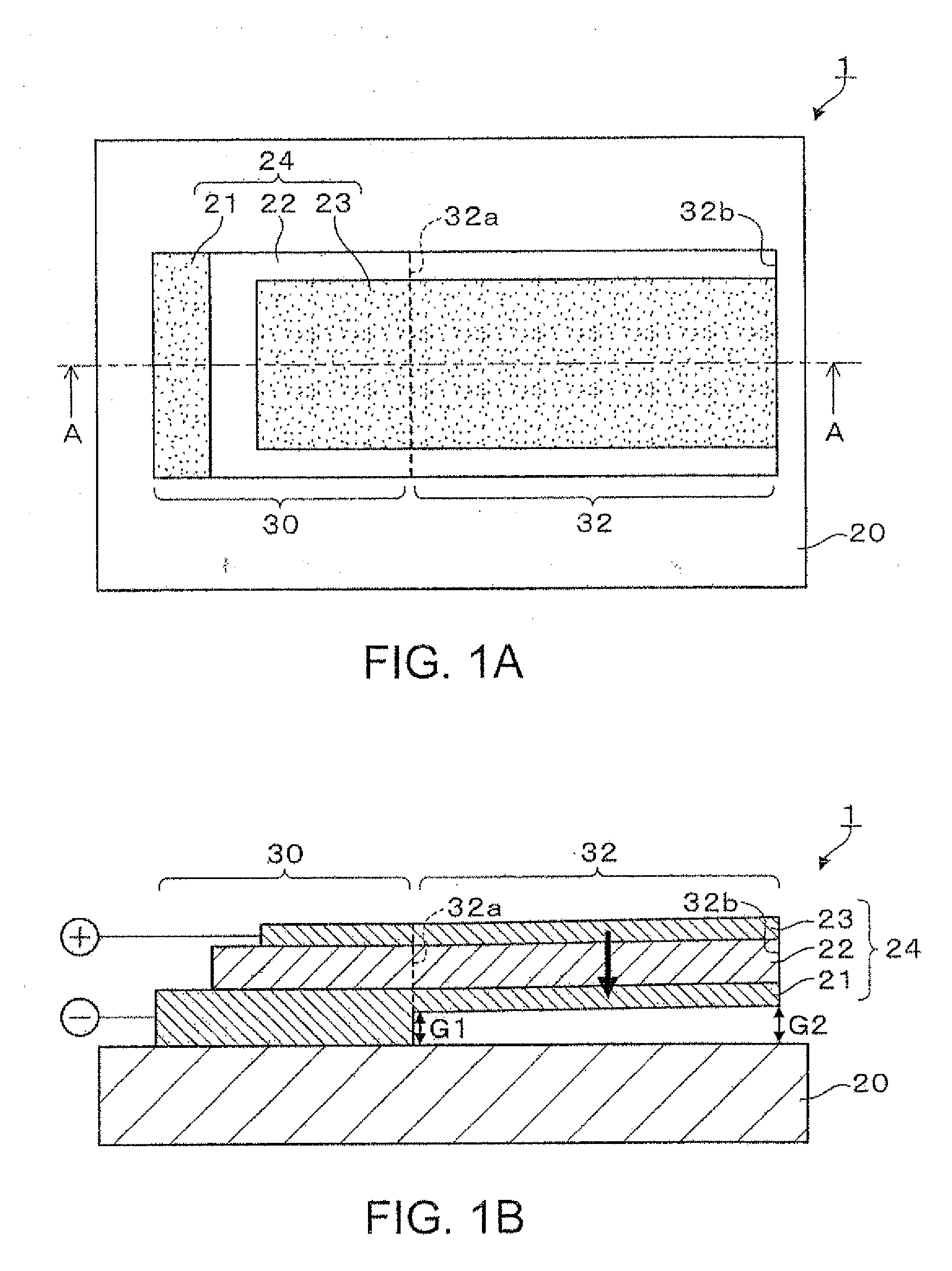
[0038]Firstly, a schematic configuration of the piezoelectric generator according to a first embodiment of the invention will be explained with reference to FIGS. 1A and 1B. FIGS. 1A and 1B are schematic diagrams showing a schematic configuration of the piezoelectric generator according to the first embodiment. For details, FIG. 1A is a schematic plan view of the piezoelectric generator, and FIG. 1B is a schematic cross-sectional view along the line A-A shown in FIG. 1A.

[0039]As shown in FIGS. 1A and 1B, the piezoelectric generator 1 according to the first embodiment is provided with a base body 20, and a piezoelectric transducer 24 including a first electrode 21, a piezoelectric body 22, and a second electrode 23 disposed in a stacked manner sequentially on the base body 20. The base body 20 is made of a ceramic material including the same component as the piezoelectric body 22. In the present embodiment, the base body 20 is made of the same ...

second embodiment

Configuration of Piezoelectric Generator

[0078]Then, a configuration of a piezoelectric generator according to a second embodiment will be explained with reference to FIGS. 6A and 6B. FIGS. 6A and 6B are schematic diagrams showing a schematic configuration of the piezoelectric generator according to the second embodiment. For details, FIG. 6A is a schematic plan view of the piezoelectric generator, and FIG. 6B is a schematic cross-sectional view along the line A-A shown in FIG. 6A.

[0079]The piezoelectric generator 2 according to the second embodiment is different from the piezoelectric generator 1 according to the first embodiment in the point that a weight 29 is disposed on the vibrating section 32, and is substantially the same in the rest of the configuration. Therefore, in the second embodiment, the constituents common to the first and second embodiments are denoted with the same reference symbols, and the explanation therefor will be omitted.

[0080]As shown in FIGS. 6A and 6B, th...

first modified example

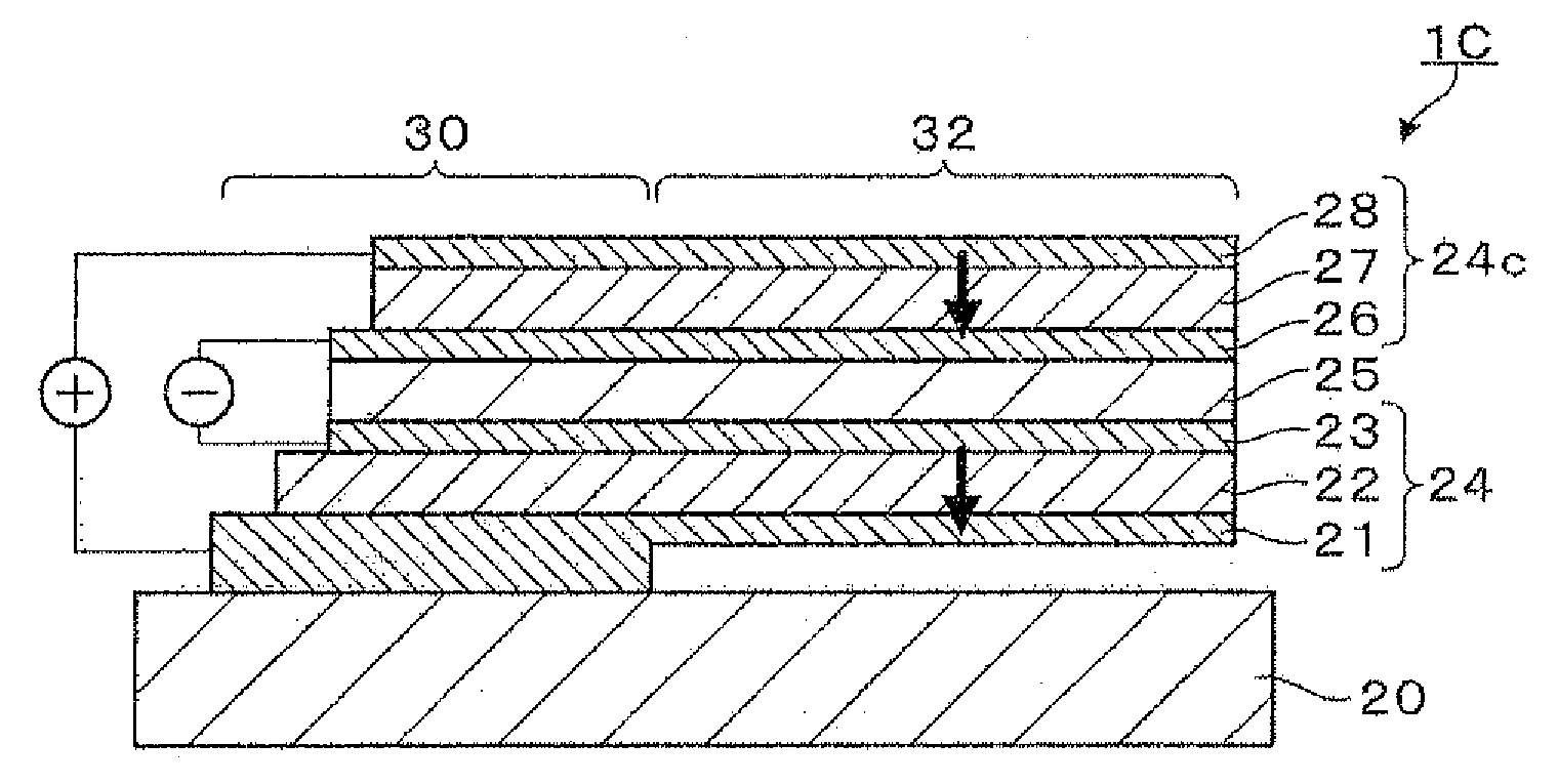
[0089]A piezoelectric generator 1A shown in FIG. 7A is further provided with a piezoelectric body 27 and a third electrode 28 stacked on the piezoelectric transducer 24 (the first electrode 21, the piezoelectric body 22, and the second electrode 23). In the piezoelectric generator 1A, a piezoelectric transducer 24a is composed of the second electrode 23, the piezoelectric body 27, and the third electrode 28. The second electrode 23 is also functions as the electrode in the piezoelectric transducer 24a. Therefore, the piezoelectric generator 1A is different from the piezoelectric generator 1 according to the first embodiment in a point that the piezoelectric transducer 24a stacked on the piezoelectric transducer 24 is provided.

[0090]According to the piezoelectric generator 1A, the electric energy due to the external vibration can be obtained from each of the plurality of piezoelectric transducers 24, 24a stacked on the base body 20. As indicated by the arrows in FIG. 7A, since the po...


PUM

PropertyMeasurementUnit
thicknessaaaaaaaaaa
thicknessaaaaaaaaaa
thicknessaaaaaaaaaa

Abstract

A piezoelectric generator includes: a base body; and at least one piezoelectric transducer disposed on the base body, and including a first electrode, a piezoelectric body, and a second electrode, wherein the piezoelectric transducer includes a support section fixed to the base body, and a vibrating section disposed apart from the base body, having one end connected to the support section and the other end set as a free end, and vibrating due to a vibration applied externally, and a distance between the other end of the vibrating section and the base body is larger than a distance between the one end of the vibrating section and the base body.

Description

[0001]This is a Division of application Ser. No. 13 / 238,778 filed Sep. 21, 2011. The prior applications, including the specifications, drawings and abstract are incorporated herein by reference in their entirety.BACKGROUND[0002]1. Technical Field[0003]The present invention relates to a piezoelectric generator, a sensor node, and a method of manufacturing a piezoelectric generator.[0004]2. Related Art[0005]There has been known a piezoelectric generator provided with a cantilevered piezoelectric transducer, and generating electric energy due to the piezoelectric effect caused by the vibration of the piezoelectric transducer (see, e.g., JP-A-11-18445 (Document 1)). The piezoelectric generator described in Document 1 is provided with a support member disposed under the piezoelectric transducer (a first electrode, a piezoelectric thin film, and a second electrode), the support member having a deformable section deformed in accordance with the piezoelectric transducer, and a support secti...

Claims


Application Information

Patent Timeline
Patent Type & Authority Applications(United States)
IPC IPC(8): H01L41/047H01L41/113H01L41/273H01L41/187H01L41/22H01L41/317H01L41/43H02N2/18
CPCH01L41/047H01L41/1132H01L41/273H02N2/188Y10T29/42H10N30/30H10N30/302H10N30/074H10N30/097H10N30/87H10N30/053
Inventor ONO, YASUHIROHIRABAYASHI, ATSUYA
Owner SEIKO EPSON CORP
Why Eureka
Try Eureka