Storage type solar power generation device and storage type solar power generation system
a solar power generation device and storage technology, applied in secondary cells servicing/maintenance, electrochemical generators, greenhouse gas reduction, etc., can solve the problems of power generation efficiency decline and photon number decrease, and achieve efficient storage of electricity, small solar cell energy loss, and efficient generation of electric power
- Summary
- Abstract
- Description
- Claims
- Application Information
AI Technical Summary
Benefits of technology
Problems solved by technology
Method used
Image
Examples
first embodiment
[0051]FIG. 6 schematically illustrates an example of the configuration of the electricity storing solar power generation device according to the invention. An electricity storing solar power generation device 10 according to the present embodiment includes, between two reflection mirrors 31 and 32 disposed to face each other and serving as reflection means, a solar cell 11 for short wavelength (a wide band gap cell), a solar cell 12 for middle wavelength (a middle band gap cell), and a solar cell 13 for long wavelength (a narrow band gap cell) that are not electrically connected and that are disposed in series in this order from the side nearer to the light entrance opening. As the solar cells 11, 12 and 13, silicon-based solar cells, compound-based solar cells, dye-sensitized solar cells, organic thin film solar cells, and the like may be used.
[0052]Storage batteries 21, 22 and 23 are connected to the solar cells 11, 12 and 13, respectively, via electrical wiring 5.
[0053]In the inv...
second embodiment
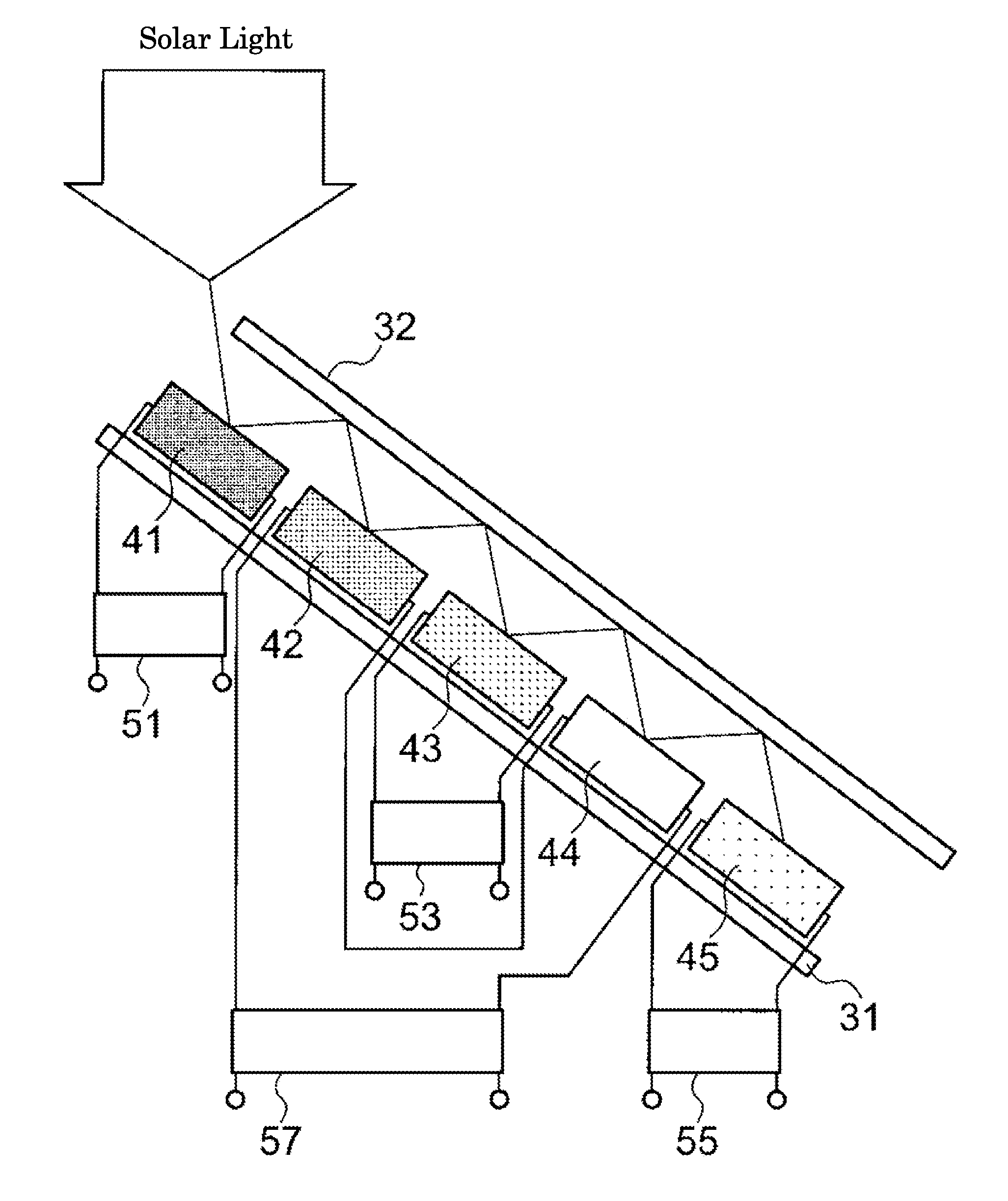
[0079]FIG. 8 schematically illustrates another example of the configuration of the electricity storing solar power generation device according to the invention. In a solar power generation device 20 according to the present embodiment, five kinds of solar cells 41, 42, 43, 44 and 45 mutually differing in spectral absorption sensitivity are alternately disposed on the inner sides of two reflection mirrors 31 and 32 disposed to face each other. In the electricity storing solar power generation device 20 according to the present embodiment, elements are arranged such that a reflected portion of light that was not absorbed by the wide band gap cell 41 disposed at the first reflection mirror 31 side can directly fall on the next cell 42 having a lower band gap and disposed at the second reflection mirror 32 side. Elements are arranged such that a reflected portion of the light that was not absorbed by the cell 42 can directly fall on the next cell 43 having a lower band gap. The cells 41...
third embodiment
[0080]FIG. 9 schematically illustrates another example of the configuration of the electricity storing solar power generation device according to the invention. As illustrated in FIG. 9, the electricity storing solar power generation device 30 according to the present embodiment has a structure in which solar cells 61 and 62, other than cell 63 having the narrowest band gap, have an optically transmitting function due to the use of, for example, a transparent electrode. In a case in which the light reflection losses in the cells 61, 62 and 63 are small, a configuration may be adopted in which the cells 61, 62 and 63 having mutually different band gaps are superposed one on another in the order from wider band gap to narrower band gap along the direction from the upper side (the light incident side) to the lower side, and light is allowed to fall on the wide band gap cell 61. The cells 61, 62 and 63 are connected to electricity storage batteries 21, 22 and 23, respectively, and the c...
PUM
| Property | Measurement | Unit |
|---|---|---|
| energy | aaaaa | aaaaa |
| band gap | aaaaa | aaaaa |
| band gap | aaaaa | aaaaa |
Abstract
Description
Claims
Application Information
 - R&D
- Intellectual Property
- Life Sciences
- Materials
- Tech Scout
- Unparalleled Data Quality
- Higher Quality Content
- 60% Fewer Hallucinations
Browse by: Latest US Patents, China's latest patents, Technical Efficacy Thesaurus, Application Domain, Technology Topic, Popular Technical Reports.
© 2025 PatSnap. All rights reserved.Legal|Privacy policy|Modern Slavery Act Transparency Statement|Sitemap|About US| Contact US: help@patsnap.com


