System and method for a self-charging battery cell

a battery cell and self-charging technology, applied in the field of self-charging battery cells, can solve the problems of waste of useful energy sources, large energy released from this event, and the use of various components of the lcr system, and achieve the effects of saving energy resources, reducing waste, and reducing the cost of storag

Inactive Publication Date: 2013-01-08
KAZEM ISMAIL
View PDF10 Cites 1 Cited by
  • Summary
  • Abstract
  • Description
  • Claims
  • Application Information

AI Technical Summary

Benefits of technology

[0009]Embodiments of the present invention provide for a method and system for the production of a self charging electric cell with a long shelf life. For example, Strontium-90 (Sr-90) radionuclide is a nuclear byproduct or waste product that emits beta electrons with a half-life of 28.8 years. In embodiments of the present invention, the emitted electrons can be applied efficiently in generating electricity. For example, the emitted electrons can be applied into a lithium ion or other cell needing electrons for recharging purposes. For example, the emitted electrons can be applied to ionizing water to supply hydrogen molecules to a nickel-hydrogen or other cell needing hydrogen molecules. For example, the emitted electrons can be converted directly into electric energy for subsequent use.
[0010]Embodiments of the present invention provide for portable containment of an essentially self-charging battery cell. Embodiments of the present invention can be used to provide stored energy for use during times of extra consumption needs. Embodiments of the present invention provide for a relatively inexpensive and efficient provision of stored energy.
[0026]Embodiments of the present invention provide for a longlife, inexpensive, reliable, relatively easy to make, and relatively easy to use system and method. Strontium-90 is a product or waste product of a nuclear reaction, and is converted into a useful source from which electric current / voltage can be obtained in embodiments of the present invention.

Problems solved by technology

The energy released from this event is very large.
Unfortunately, the LCR system requires the use of various components which can fail overtime, long before the energy source is depleted.
This then can lead to a waste of useful energy sources, as well as of other robust components of the battery system such as, for example, the protective housing.

Method used


Image

  • System and method for a self-charging battery cell
  • System and method for a self-charging battery cell
  • System and method for a self-charging battery cell

Examples


Embodiment Construction

[0037]The following description provides specific details for a thorough understanding of, and enabling description for, various embodiments of the technology. One skilled in the art will understand that the technology may be practiced without many of these details. In some instances, well-known structures and functions have not been shown or described in detail to avoid unnecessarily obscuring the description of the embodiments of the technology. It is intended that the terminology used in the description presented below be interpreted in its broadest reasonable manner, even though it is being used in conjunction with a detailed description of certain embodiments of the technology. Although certain terms may be emphasized below, any terminology intended to be interpreted in any restricted manner will be overtly and specifically defined as such in this Detailed Description section.

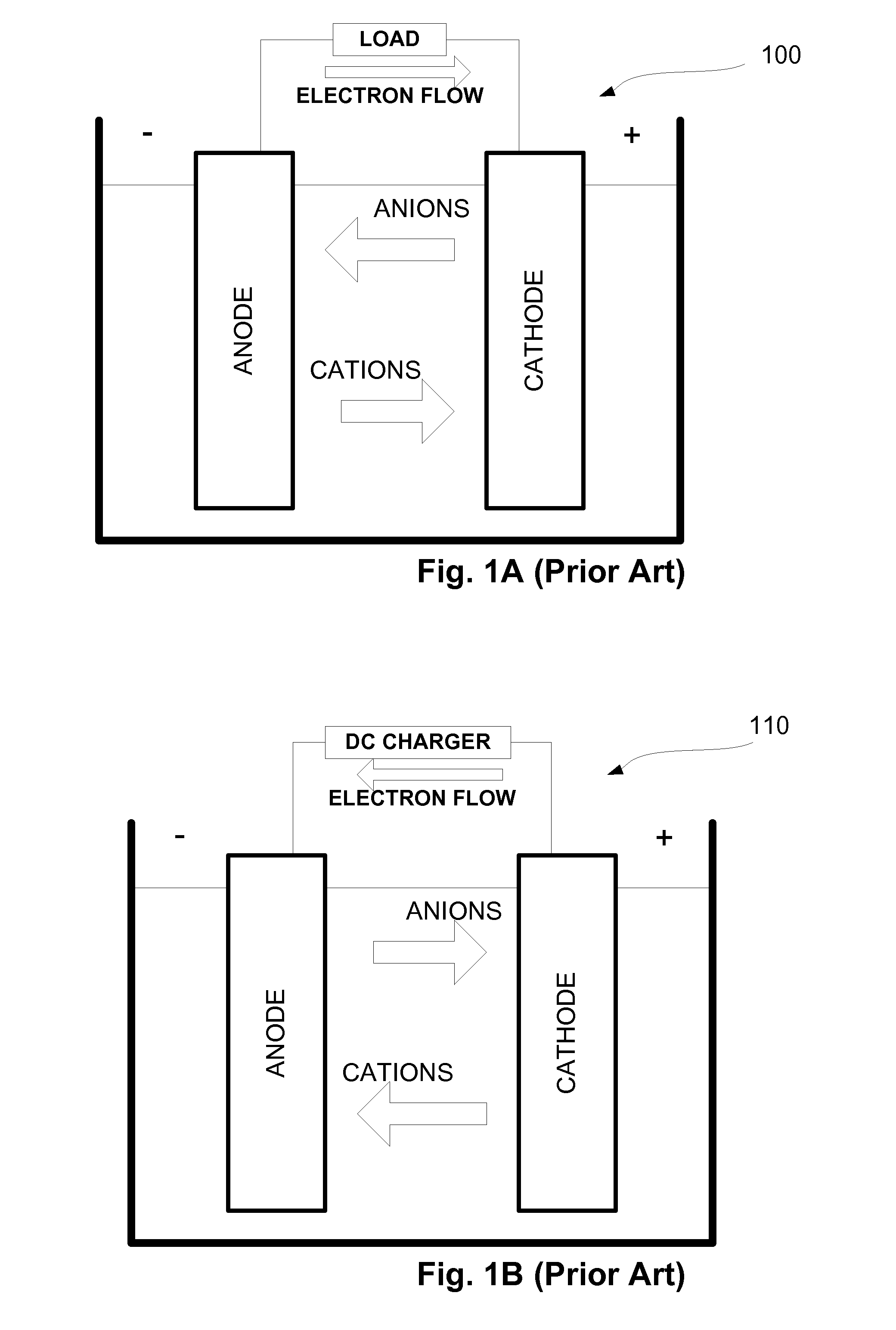
[0038]FIG. 1A illustrates a diagram of an example battery cell system 100 according to available system...


PUM

PropertyMeasurementUnit
electric energyaaaaaaaaaa
electric currentaaaaaaaaaa
voltageaaaaaaaaaa

Abstract

A system and method for a self-charging battery cell are provided in which beta emissions from a Strontium-90 source are obtained by a sensor device and converted into electric energy. In embodiments, a scintillation device is used to intake emissions from a Strontium-90 source, and consequently emit a light or plurality of light flashes. A sensor device, e.g., a photodiode, is utilized to convert the light or plurality of light flashes into electric voltage, current and / or energy.

Description

FIELD OF INVENTION[0001]The present invention relates generally to using existing emissions to obtain electric energy.BACKGROUND[0002]Energy conservation and use are hotly discussed topics. Traditionally, electric energy has been transformed, for example, from heat, water, wind, coal, and manmade chemical reactions. Such resources are currently plentiful, however, many must be resourced and replenished for the continued obtainment of electric energy. Consequently, scientists have looked elsewhere for additional sources of electric energy, especially sources which may be readily converted and in a clean fashion, or, if possible, recycling used resources.[0003]Various battery types are available in the current market. Some may use an energy source which provides energy from a beta voltaic effect. Beta decay of electrically charged particles is used to provide energy. A beta decay is electrically charged particle expelled from a nucleus. A moving charged particle, such as beta decay, y...

Claims


Application Information

Patent Timeline
Patent Type & Authority Patents(United States)
IPC IPC(8): H01M10/46G21H1/00H01L35/30
CPCH01M10/46H01M10/0525Y02E60/10
Inventor KAZEM, ISMAIL
Owner KAZEM ISMAIL
Why Eureka
Try Eureka