
Current detection device

Inactive Publication Date: 2014-08-21
TOYOTA JIDOSHA KK +1
View PDF3 Cites 0 Cited by
  • Summary
  • Abstract
  • Description
  • Claims
  • Application Information

AI Technical Summary

Benefits of technology

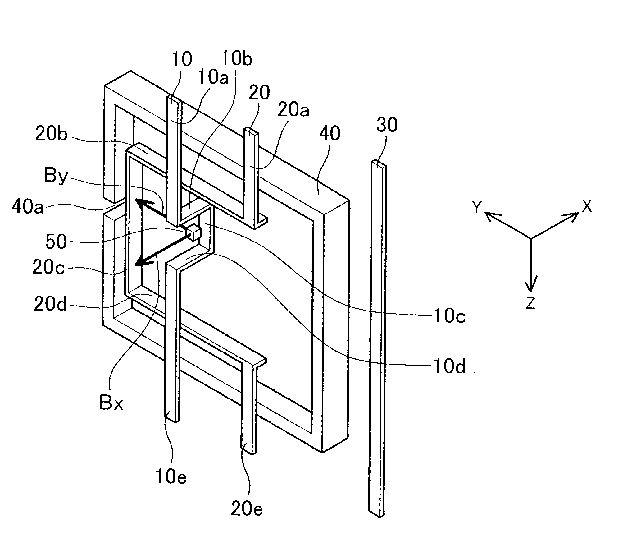
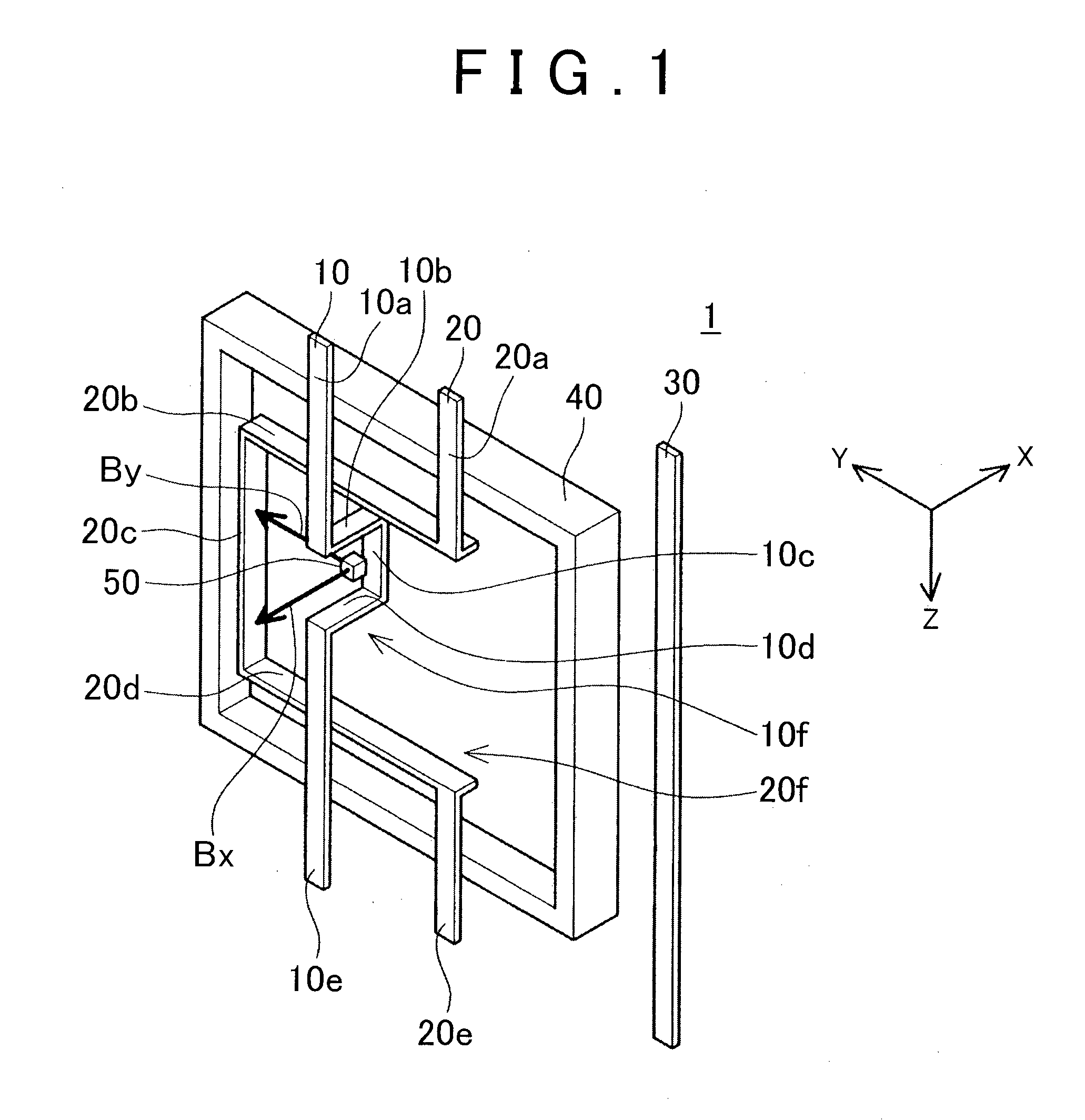
The present invention provides a current detection device with improved sensitivity. The device has two current paths that are parallel to each other, and a z-coordinate range that includes the z-coordinate ranges of both current paths. This allows for the placement of magnetic flux density detection devices in the same position, even though they are separately set up for detecting the magnetic flux density in different directions. Additionally, the placement of the detection devices at the same position results in enhanced detection sensitivity. This applies when the current paths extend in parallel and the detection devices are set up to detect the values of current passing through one path without being affected by the current passing through the other path.

Problems solved by technology

However, when the spacing between two current paths is narrow, the extent of a region where the magnetic field by the first current path is distributed becomes narrow, which makes it difficult to arrange the first magnetic flux density detection device in such a narrow region.
Likewise, a region where the magnetic field by the second current path is distributed also becomes narrow, which makes it difficult to arrange the second magnetic flux density detection device within the region.

Method used


Image

  • Current detection device
  • Current detection device
  • Current detection device

Examples


Embodiment Construction

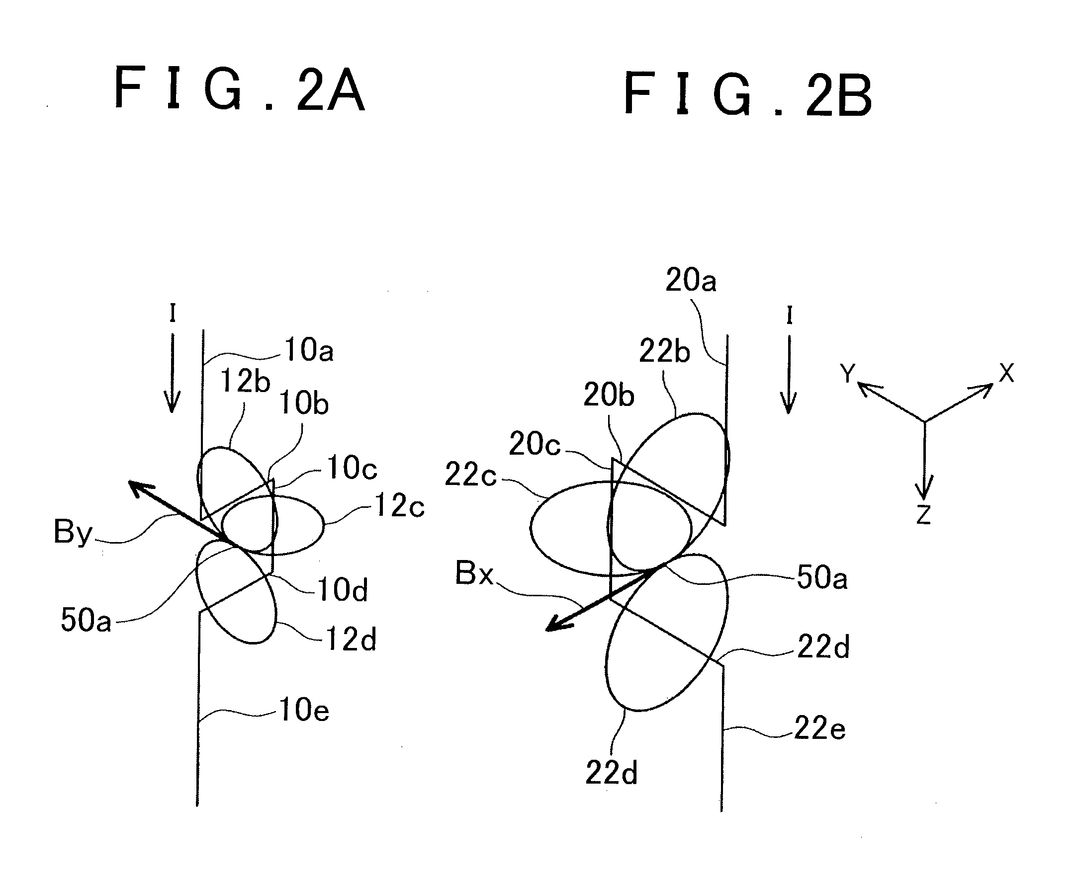
[0033]First, the primary features of the embodiments shown below are listed. A current path is made of a metal band (bus bar). Current paths are arranged in the order corresponding to a first current path, a second current path and a third current path. The direction in which each of the first current path, the second current path and the third current path extends is defined as the z-direction. The direction starting from the third current path and heading toward the first current path via the second current path is defined as the y-direction. An x-direction bent portion is formed in the first current path and a y-direction bent portion is formed in the second current path. The y-direction bent portion extends beyond the first current path in a y-z plane. The x-direction bent portion intrudes inside the y-direction bent portion. A two-component magnetic flux density detection device is disposed inside of the x-direction bent portion. The two-component magnetic flux density detectio...


PUM


Abstract

A first bent portion whose extending direction changes in the order of +z, +x, +z, −x, and +z is formed in a first current path, wherein a direction in which two current paths extend in parallel as the z-direction of the x-y-z orthogonal coordinate system and a second bent portion whose extending direction changes in the order of +z, +y, +z, −y, and +z is formed in a second current path. Either one of the z-coordinate range of the middle part of the first bent portion and the z-coordinate range of the middle part of the second bent portion includes the other one and a magnetic flux density detection device that detects the x-direction magnetic flux density and the y-direction magnetic flux density is disposed within the included z-coordinate region.

Description

BACKGROUND OF THE INVENTION[0001]1. Field of the Invention[0002]The present invention provides a technique that independently detects the value of a current passing through each of two current paths that extend in parallel. In other words, the invention provides a technique that detects the value of a current passing through a first current path (hereinafter referred to as a first current value) without being affected by a current passing through a second current path and detects the value of the current passing through the second current path (hereinafter referred to as a second current value) without being affected by the current passing through the first current path when the first current path and the second current path extend in parallel. When three-phase alternating currents are passed through three current paths, the value of a current passing through a third current path (hereinafter referred to as a third current value) can be calculated from the first current value and se...

Claims


Application Information

Patent Timeline
IPC IPC(8): G01R19/00G01R33/09G01R33/07
CPCG01R19/0092G01R33/093G01R33/07G01R15/207G01R15/202
Inventor YAMAGUCHI, TATSUYUKI
Owner TOYOTA JIDOSHA KK
Learn More