
Load control device, electric power steering device, and method for controlling load control device

a technology of load control device and electric power steering device, which is applied in the direction of instruments, base element modifications, transportation and packaging, etc., can solve the problem and achieve the effect of reducing the detection accuracy of the current value of the inverter circui

Active Publication Date: 2016-08-02
KYB CORP
View PDF5 Cites 0 Cited by
  • Summary
  • Abstract
  • Description
  • Claims
  • Application Information

AI Technical Summary

Benefits of technology

The patent text is discussing the problem of voltage detection in a circuit and how it can be influenced by common-mode rejection ratio and input offset voltage. The technical effect of this patent is to provide a load control device that can accurately detect the current value within a circuit.

Problems solved by technology

Therefore, there may be an error between the voltage detected by the voltage detection device and the actual voltage between the input terminals, and thus the detection precision of the current value of the inverter circuit may decrease.

Method used


Image

  • Load control device, electric power steering device, and method for controlling load control device
  • Load control device, electric power steering device, and method for controlling load control device
  • Load control device, electric power steering device, and method for controlling load control device

Examples


Embodiment Construction

[0015]Hereinafter, embodiments of the present invention are described with reference to the drawings.

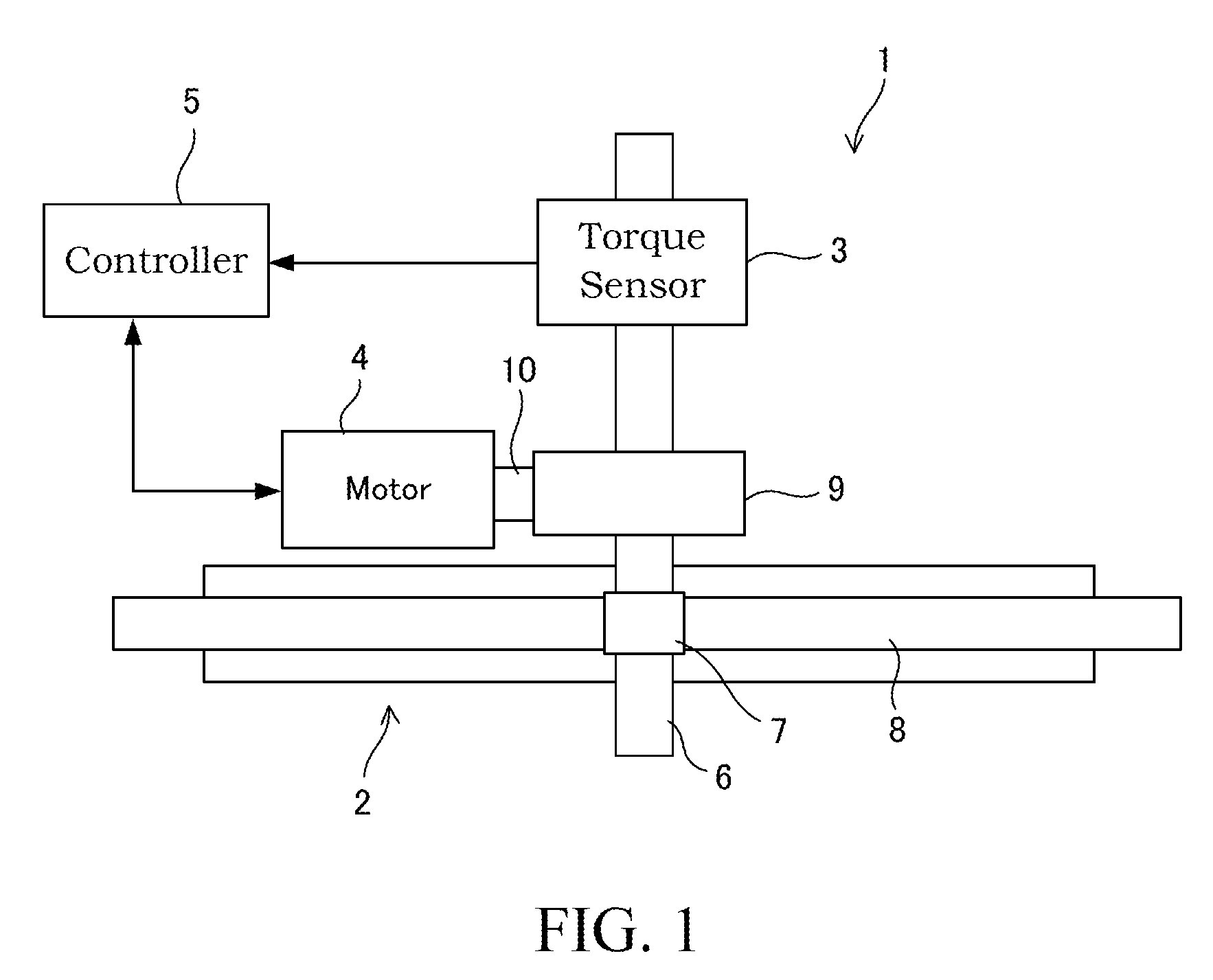
[0016]FIG. 1 is a schematic view illustrating an electric power steering device 1 equipped with a motor control device according to an embodiment of the present application.

[0017]The electric power steering device 1 includes a steering mechanism 2 that is connected to a steering wheel (not illustrated) and steers a vehicle wheel (not illustrated), a torque sensor 3 that detects an input torque, an electric motor 4 (hereinafter referred to simply as the “motor 4”) that serves as a load which imparts an assist torque to the steering mechanism 2, and a controller 5 that serves as a load control means into which a detection signal from the torque sensor 3 is input and which controls an output of the motor 4.

[0018]The steering mechanism 2 includes a steering shaft 6 that is connected to the steering wheel, a pinion 7 formed on the steering shaft 6, and a rack 8 that engages with the pinio...


PUM


Abstract

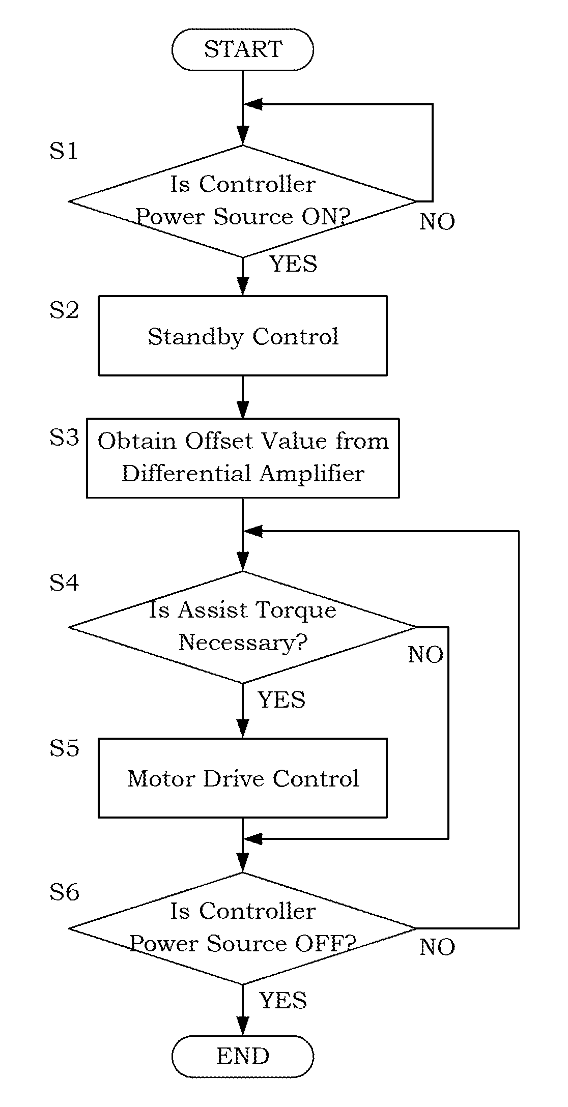
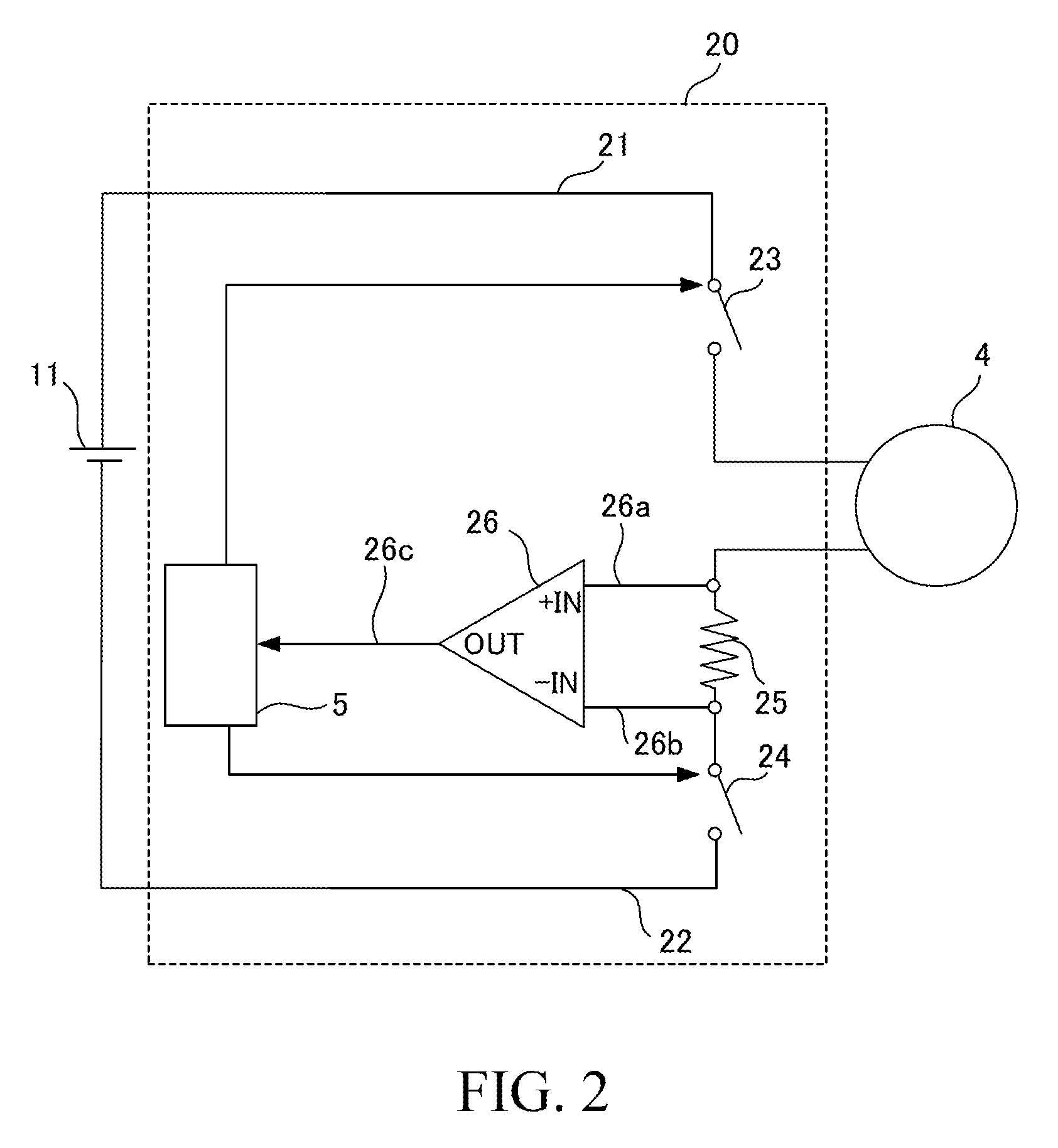
A load control device includes a load control means that drives a load, a current detection resistor, a differential amplifier and a current calculation means. The load control means can switch between a standby state a drive state, a state in which a first of the switching elements is turned ON and a second of the switching elements is turned OFF and a state in which the first of the switching elements is turned OFF and the second of the switching elements is turned ON being alternately repeated in the standby state, in which both of the switching elements are turned ON in the drive state. The current calculation means calculates a current that flows to the current detection resistor on the basis of a value output from the differential amplifier in the drive state and an offset value output from the differential amplifier in the standby state.

Description

TECHNICAL FIELD[0001]The present invention relates to a load control device, an electric power steering device, and a method for controlling the load control device.BACKGROUND ART[0002]In a well-known electric power steering device, an assist force corresponding to a steering torque input into a steering wheel is generated by a motor. Such an electric power steering device includes an inverter circuit interposed between the motor and a power source, and a controller that ON / OFF controls switching elements of the inverter circuit. The switching elements switch a connection between the power source and the motor between an ON state and an OFF state on the basis of a PWM signal transmitted from the controller.[0003]JP2007-189825A discloses an electric power steering device like that described above which comprises a voltage detection device in which a current detection resistor is serially interposed between the power source and the switching elements and a voltage drop generated by th...

Claims


Application Information

Patent Timeline
Patent Type & Authority Patents(United States)
IPC IPC(8): B62D6/00B62D5/04G01R1/20
CPCB62D5/0481B62D5/0463G01R1/203H02P2205/05
Inventor NAGAE, KOUKIOWAKI, JUNICHI
Owner KYB CORP
Learn More