Passive infra-red detectors

a detector and infra-red technology, applied in radiation pyrometry, instruments, material analysis, etc., can solve the problems of significant thermal interference signals, false alarms, and insufficient detection reliability, so as to reduce the “undesired signals” and improve the signal processing

Active Publication Date: 2007-01-25
TYCO FIRE & SECURITY GMBH
View PDF41 Cites 66 Cited by
  • Summary
  • Abstract
  • Description
  • Claims
  • Application Information

AI Technical Summary

Benefits of technology

[0026] A principal objective of the present invention is to manage interference and substantially decrease the “undesired signals” detected by a sensor, and as a result to increase the ratio between the “desired signal” and the “undesired signals”, arising from interference, at every point in time. An additional o

Problems solved by technology

However, when installed outdoors or in harsh environments, such detectors are subject to operational conditions of various types, which cause false alarms.
Extreme environmental conditions and extreme changes thereof which cause significant thermal interference signals.
Although such detectors perform better outdoors

Method used


Image

  • Passive infra-red detectors
  • Passive infra-red detectors
  • Passive infra-red detectors

Examples


Embodiment Construction

[0188] For the sake of clarity of description throughout, the following definitions are employed generally throughout.

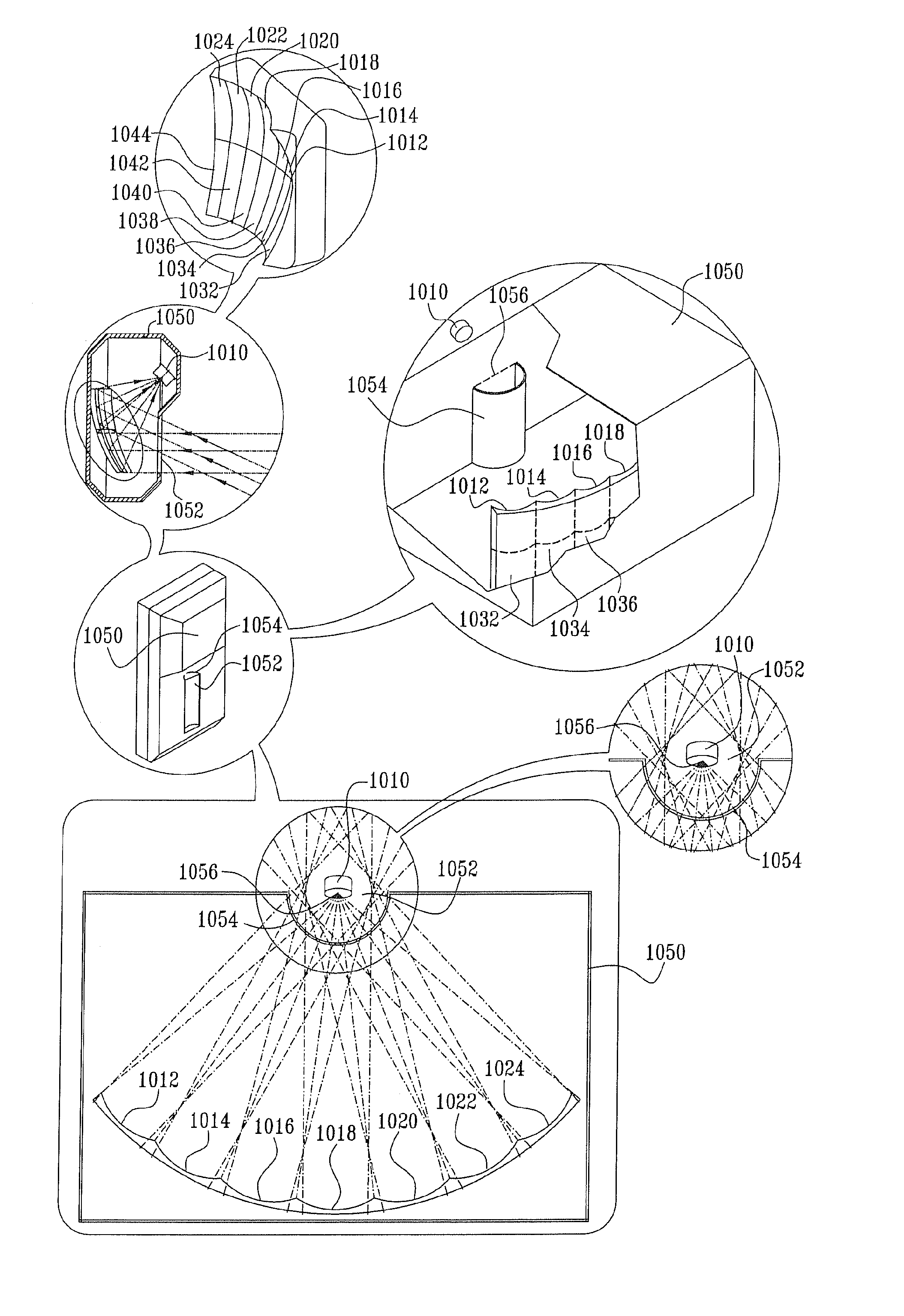
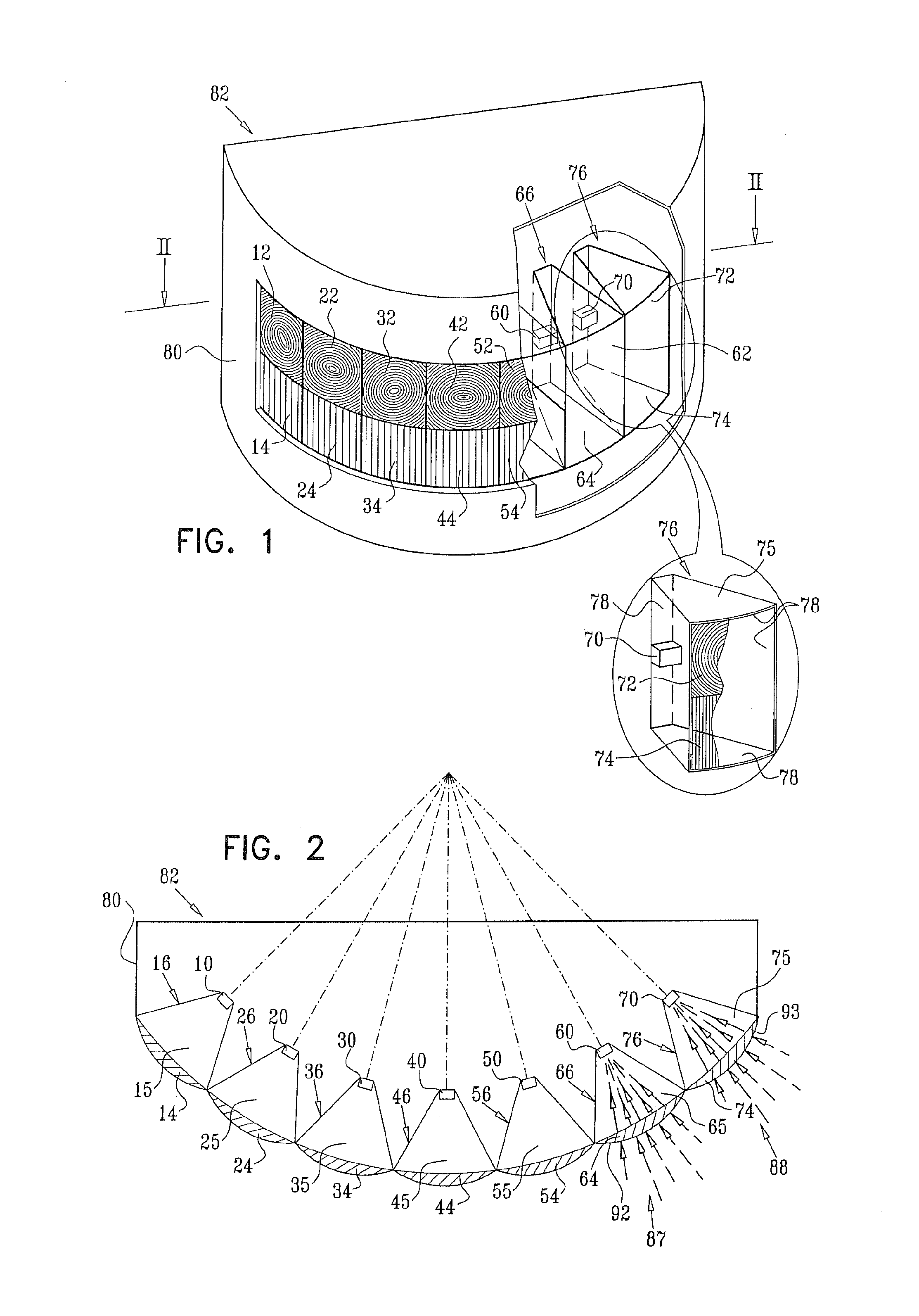
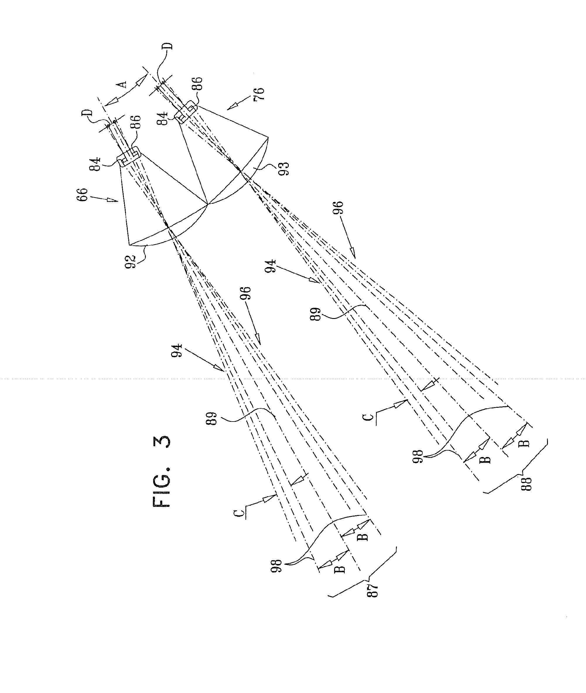
[0189] A “zone” is defined to include fingers of radiation, each corresponding to a detection region seen by a single element of a sensor through an optical segment, and the region or regions therebetween. Thus, when dual element sensors are employed, each zone includes two fingers.

[0190] A “sub field-of-view” is defined to include one or more zones and the region or regions therebetween.

[0191] A “field-of-view” is defined to include one or more sub fields-of-view.

[0192] It is important to note that in detectors designed to protect wide azimuthal areas, the field-of-view may be divided into multiple sub fields-of-view, which typically correspond in number to the number of lens or mirror segments in the uppermost row of optical elements.

[0193] The term “azimuth” refers to the angular extent of a zone, sub field-of-view or field-of-view in a plane wherein expected...


PUM


Abstract

A passive infra-red detector including at least three sub-detectors, each sub-detector being operative to receive infra-red radiation from a corresponding one of at least three sub fields-of-view, each sub field-of-view being exclusively defined by an optical element which does not define any other sub field of view, the sub fields-of-view being angled with respect to each other, adjacent ones of the sub fields-of-view being separated by a gap of no more than 30 degrees and at least one of the sub fields-of-view having at least one of the following characteristics: extending over no more then 45 degrees in azimuth; and including not more than three azimuthally distributed detection zones, and signal processing circuitry, operative to receive output signals from the sub detectors and to provide a motion detection output.

Description

REFERENCE TO RELATED APPLICATIONS [0001] Reference is made to U.S. Provisional Patent Application No. 60 / 664,231, entitled PASSIVE INFRA-RED DETECTORS AND TECHNIQUES EMPLOYING SUB-DETECTORS, filed Mar. 21, 2005, the disclosure of which is hereby incorporated by reference and priority of which is hereby claimed pursuant to 37 CFR 1.78(a) (4) and (5)(i).FIELD OF THE INVENTION [0002] The present invention relates to passive infrared detectors generally. BACKGROUND OF THE INVENTION [0003] Passive infrared detectors known in the art have an optical design which is usually based on the use of multiple optical elements, such as lens or mirror segments, arranged in one or more rows, each row including one or more segments. The segments within the rows are arranged with their optical axes spread azimuthally in a plane, generally parallel to the horizontal, or inclined with respect to the horizontal. Each of the segments is arranged to focus IR energy emanating from a pre-defined detection zo...

Claims


Application Information

Patent Timeline
IPC IPC(8): G01J5/02
CPCG01J5/0025G01J5/026G01J5/08G01J5/0806Y10S250/01G01J5/0862G01J5/089G08B13/193G08B29/18G01J5/0846G01J5/0802G01J5/07
Inventor ZHEVELEV, BORISKOTLICKI, YAACOVLAHAT, MICHAEL
Owner TYCO FIRE & SECURITY GMBH
Why Eureka
Try Eureka