
Motor drive device

a technology of motor drive and drive device, which is applied in the direction of electronic commutation motor control, motor/generator/converter stopper, dynamo-electric converter control, etc., can solve the noise of current sensor detection, affecting the efficiency of motor operation, and lowering the duty ratio of current applied to the motor more often. , to achieve the effect of simple configuration and high precision

Active Publication Date: 2015-10-01
DENSO CORP
View PDF0 Cites 1 Cited by
  • Summary
  • Abstract
  • Description
  • Claims
  • Application Information

AI Technical Summary

Benefits of technology

The present disclosure provides a motor drive device that can accurately detect the power source current value and prevent overload using a simple configuration. The device can sample the current repeatedly and set the peak value as the newest value if it is greater than the previous value. By comparing the new peak value with a specific threshold value, the device can make an overload determination and detect the power source current value with high precision. Overall, the motor drive device can accurately detect power source current and prevent overload, ensuring safe and efficient operation.

Problems solved by technology

However, spikes in noise are generated sporadically in the current between the power source and the inverter circuit, such that there is a possibility that the detection of the current sensor is affected by the noise.
However, in the electric drive device described in JP-A No. 2011-50202, there is a possibility of significant error, such that the detected current value is lower than the actual current value, due to high frequency components of the signal being excessively eliminated by the low pass filter.
There is accordingly a possibility that the duty ratio of current applied to the motor is more frequently lowered, impairing efficient operation of the motor.
There is also a possibility that the product incurs an increase in cost due to mounting a filter such as the low pass filter to the circuit.

Method used


Image

  • Motor drive device
  • Motor drive device
  • Motor drive device

Examples


Embodiment Construction

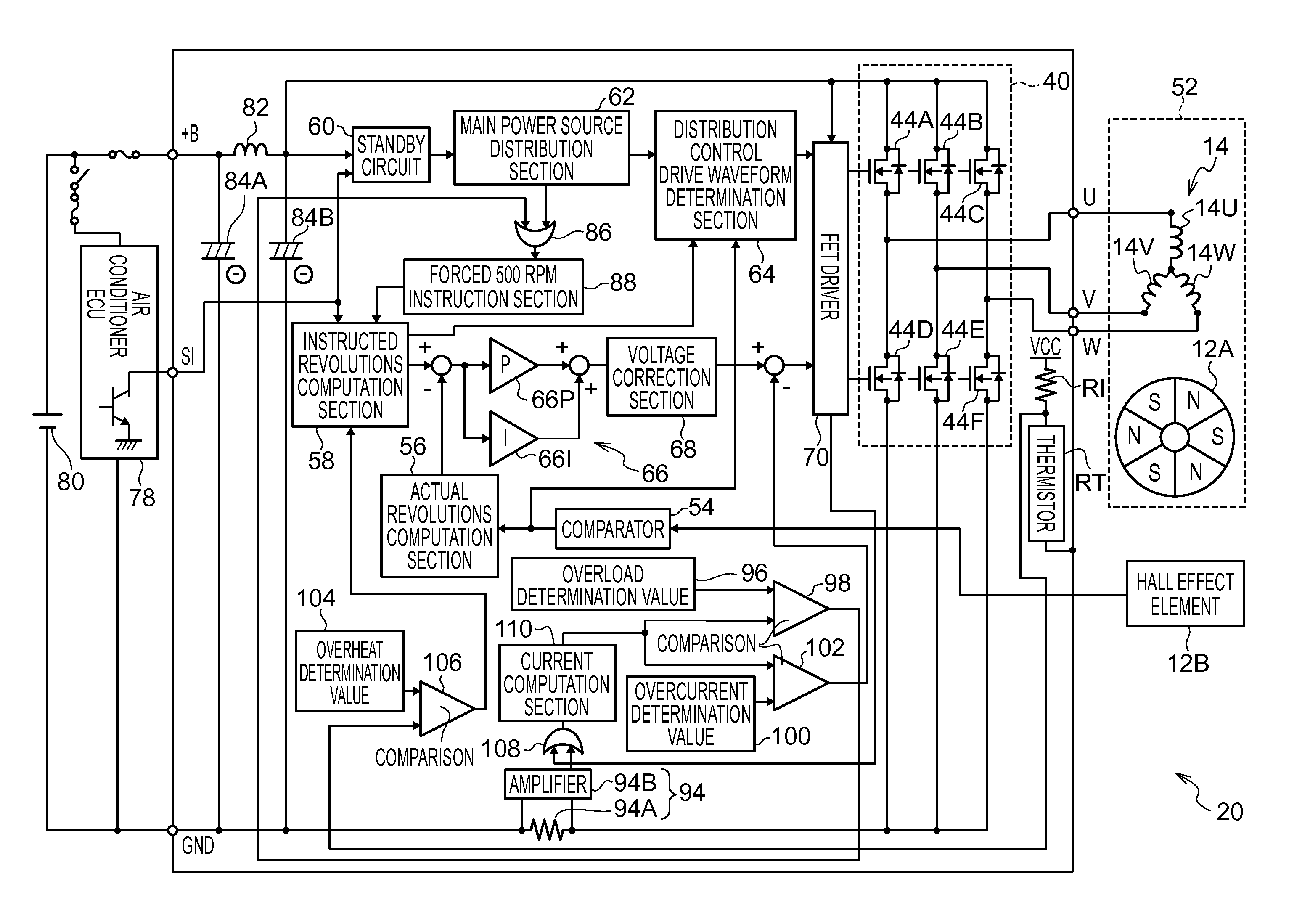
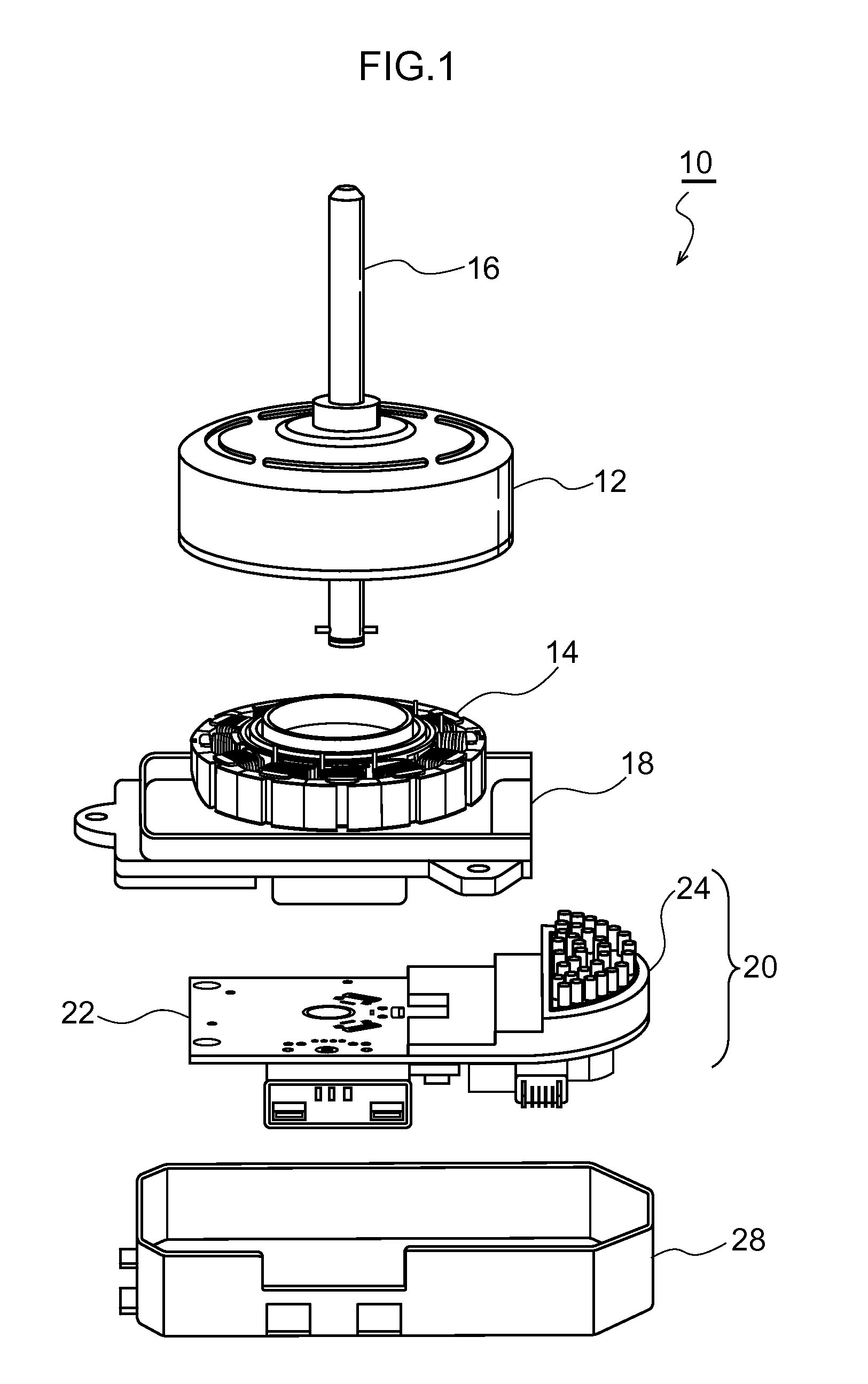
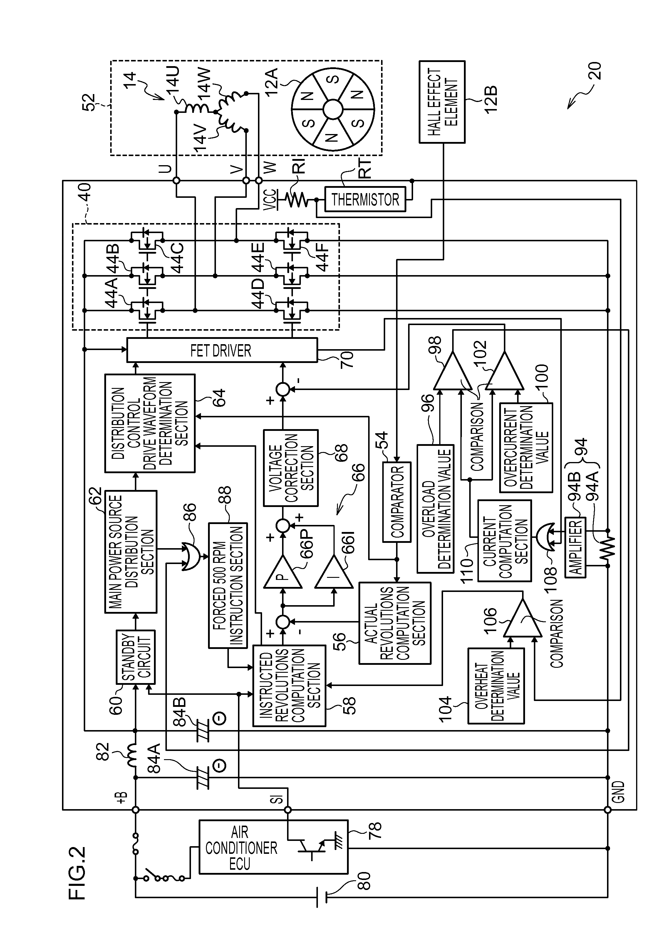
[0024]FIG. 1 is a schematic view illustrating a configuration of a motor unit 10 employing a motor drive device 20 according to an exemplary embodiment. The motor unit 10 according to the present exemplary embodiment in FIG. 1 is, for example, what is known as a blower motor unit, employed to convey air in a vehicle air conditioner.

[0025]The motor unit 10 according to the present exemplary embodiment is a brushless DC motor (hereafter referred to as “motor”), and is a three phase motor with an outer rotor structure, with a rotor 12 provided to the outside of a stator 14. The stator 14 is an electromagnet configured by a conductive wire wound around a core member, and is configured with three phases, namely a U phase, a V phase, and a W phase. A motor drive device 20, described later, controls to switch the polarity of the magnetic field generated by the electromagnet, such that the U phase, the V phase, and the W phase of the stator 14 respectively generate what is known as a rotati...


PUM


Abstract

There is provided a motor drive device including, a current detection section that detects current flowing between a power source and an inverter circuit generating voltage to be supplied to a motor, a voltage control section that outputs a first control signal to cause the inverter circuit to generate a voltage for rotating the motor at a rotation speed based on an instructed value, and a rotation speed suppression section that, in cases in which current, detected by the current detection section at a timing at which a voltage generated by the inverter circuit rises from low level to high level, is a predetermined threshold value or higher, outputs a second control signal to the voltage control section to cause the inverter circuit to generate a voltage for rotating the motor at a lower rotation speed than the rotation speed based on the instructed value.

Description

CROSS-REFERENCE TO RELATED APPLICATION[0001]This application claims priority under 35 USC 119 from Japanese Patent application No. 2014-062579 filed on Mar. 25, 2014, the disclosure of which is incorporated by reference herein.BACKGROUND[0002]1. Technical Field[0003]The present disclosure relates to a motor drive device.[0004]2. Related Art[0005]As a blower motor employed to convey air in a vehicle air conditioner, sometimes brushless DC motors are employed in which a rotor configured by a permanent magnet tracks a rotating magnetic field generated by a stator, provided along the circumferential direction of the rotor, and rotates. Since, unlike brushed DC motors, brushless DC motors do not have a sliding configuration, power consumption is low compared to brushed DC motors, and are compatible with faster rotation speeds.[0006]When the number of revolutions are increased in the motor, the load on the motor and a motor drive device that drives the motor increases. In the motor drive ...

Claims


Application Information

Patent Timeline
IPC IPC(8): H02P6/00
CPCH02P6/002H02P6/28
Inventor YAMAGUCHI, KOSUKESAIGUSA, DAIJIRO
Owner DENSO CORP
Learn More