Earphone microphone

a microphone and earphone technology, applied in the field of earphone microphones, can solve the problems of difficult downsizing difficult to reduce the size of the main body casing, and increasing the cost of the main body, so as to suppress the input of the output sound of the speaker and suppress the noise

Inactive Publication Date: 2014-08-21
FUNAI ELECTRIC CO LTD
View PDF5 Cites 14 Cited by
  • Summary
  • Abstract
  • Description
  • Claims
  • Application Information

AI Technical Summary

Benefits of technology

[0011]With this structure, the earphone microphone includes the single speaker. In addition, the sound output path branches into the one path communicating with outside of the main body casing and the other path communicating with the second sound input path. For this reason, the output sound from the speaker propagates to the first microphone via the one path and the first sound input path, and also propagates to the second microphone via the other path and the second sound input path. Further, the earphone microphone inputs sound from the outside sound source by amplifying the sound signal output from at least one of the first and second microphones, and suppresses input of the output sound from the speaker. For this reason, the earphone microphone can realize the echo suppression function of the output sound from the speaker without using a plurality of speakers. Further, the earphone microphone can transmit input sound while suppressing noise due to the output sound from the speaker. Therefore, it is possible to provide an earphone microphone having the echo suppression function that is inexpensive and can be downsized.

Problems solved by technology

Consequently, there is a problem that the echo component is mixed as noise into the voice sound transmitted from the earphone microphone.
Therefore, there is a problem that it is difficult to downsize the main body casing.
In addition, there is another problem that it becomes relatively expensive because of manufacturing cost.

Method used


Image

  • Earphone microphone
  • Earphone microphone
  • Earphone microphone

Examples


first embodiment

[0037](Structure of Earphone Microphone)

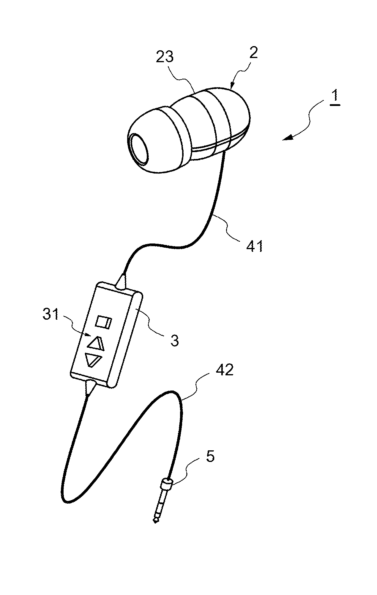
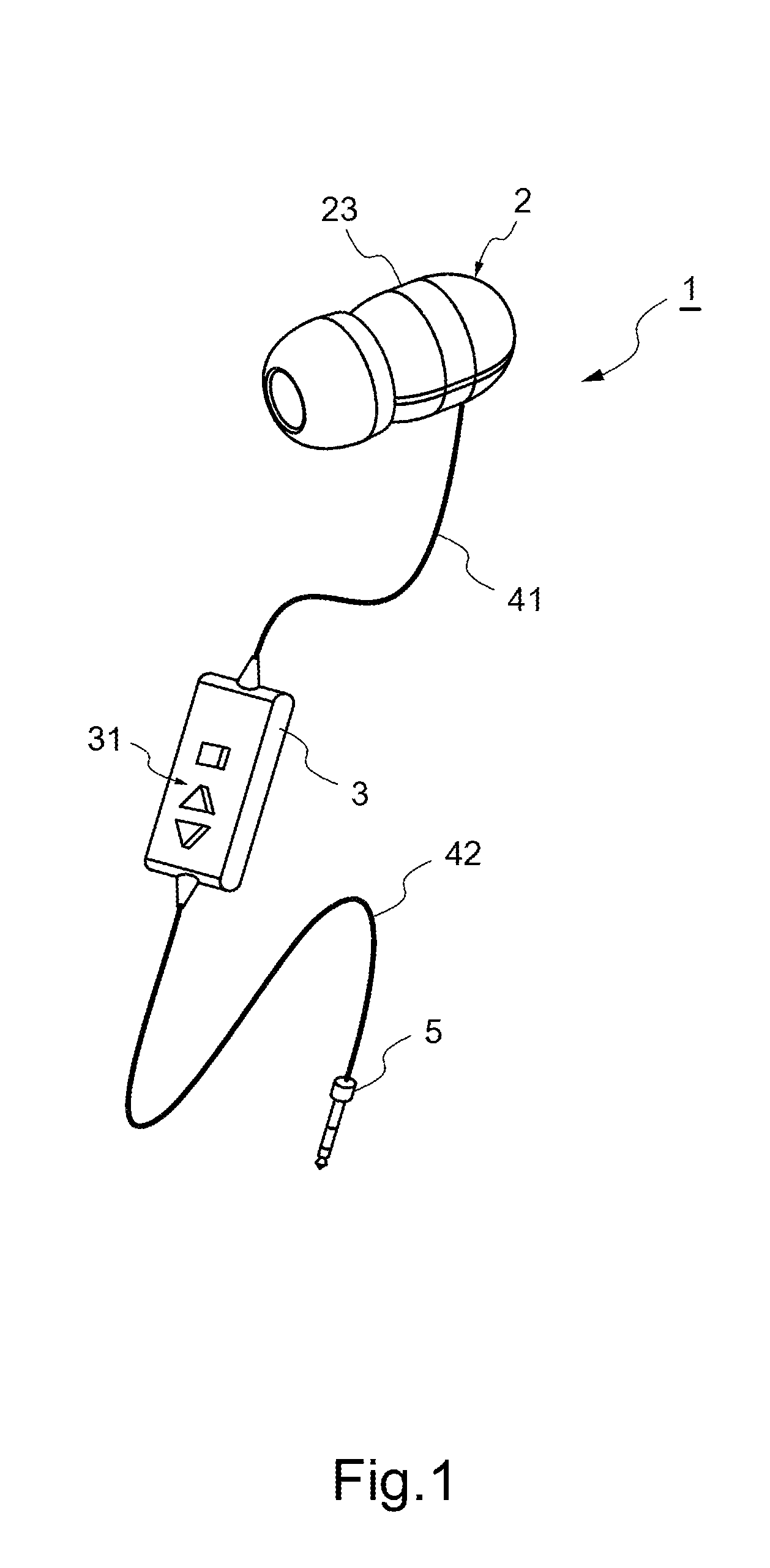
[0038]FIG. 1 is an outside perspective view of an earphone microphone. An earphone microphone 1 is a sound input and output device connected to electronic equipment (not shown) such as a cellular phone, for example. As illustrated in FIG. 1, the earphone microphone 1 includes a main body 2, a control unit 3, a first cable 41, a second cable 42, and a connector 5.

[0039]The main body 2 is inserted into a user's ear, so as to output sound and to input sound from an outside sound source (for example, user's speaking voice). Note that specific structures of the main body 2 and the control unit 3 are described later. The first cable 41 is a signal line that is connected between the main body 2 and the control unit 3 so as to transmit and receive signals between the main body 2 and the control unit 3. The second cable 42 is a signal line that is connected between the control unit 3 and the connector 5 so as to transmit and receive signals via the con...

second embodiment

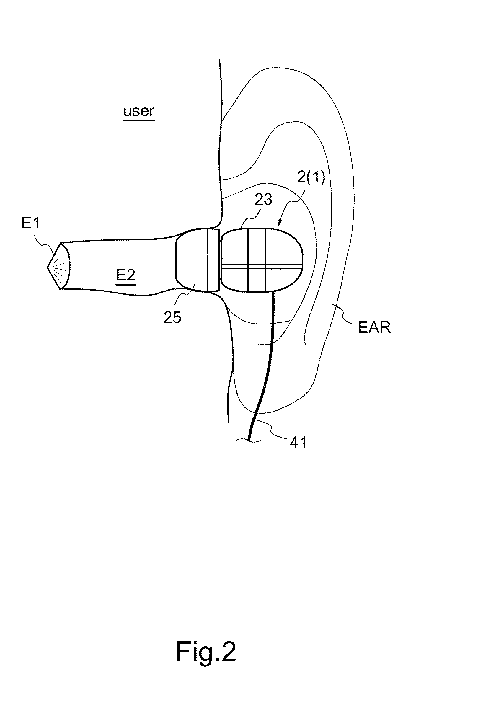
[0080]Next, the earphone microphone 1 of a second embodiment is described. FIG. 12 is a conceptual structural diagram of the earphone microphone according to the second embodiment. In addition, FIG. 13 is a front view of a main body viewed from the user's external auditory meatus in the second embodiment.

[0081]As illustrated in FIGS. 12 and 13, in the second embodiment, a fourth aperture 231d is further formed in the insertion part 23a on the surface on which the second and third apertures 231b and 231c are formed. In addition, the acoustic space inside the main body casing 23 further includes a third sound input path 235 that communicates outside of the main body casing 23 with the second sound input path 234 via the fourth aperture 231d. Other structures are the same as in the first embodiment. In the following description, the same structure as in the first embodiment is denoted by the same numeral, and description thereof is omitted.

[0082](Structure of Earphone Microphone)

[0083]...


PUM


Abstract

An acoustic space including a sound output path, first and second sound input paths is formed in a main body casing of an earphone microphone. Output sound from a speaker propagates in the sound output path. Sound input to a first microphone propagates in the first sound input path communicating with outside. Sound input to a second microphone propagates in the second sound input path. The sound output path branches into one path communicating with the outside of the main body casing and the other path communicating with the second sound input path. The earphone microphone amplifies a sound signal output from at least one of the first and second microphones so as to input sound from a sound source outside the main body casing, and suppresses input of the output sound.

Description

[0001]This application is based on Japanese Patent Application No 2013-030793 filed on Feb. 20, 2013, contents of which are hereby incorporated by reference.BACKGROUND OF THE INVENTION[0002]1. Field of the Invention[0003]The present invention relates to an earphone microphone, and particularly to an earphone microphone including a speaker and a microphone.[0004]2. Description of Related Art[0005]Conventionally, there is known an earphone microphone including a speaker and a microphone. Using the earphone microphone set in the ear, a user can hear sounds such as voice output from the speaker while transmitting sounds such as user's voice input to the microphone. Therefore, the earphone microphone is used for handsfree communication using a cellular phone or the like.[0006]However, the sound output from the speaker to the user's external auditory meatus is echoed by the user's tympanum, the external auditory meatus, and the like to enter the earphone microphone as noise (echo componen...

Claims


Application Information

Patent Timeline
Patent Type & Authority Applications(United States)
IPC IPC(8): H04R1/10
CPCH04R1/1058H04R1/1083H04R1/1016H04R2201/107H04R2410/05
Inventor TANAKA, FUMINORISHIMIZU, NORIYUKI
Owner FUNAI ELECTRIC CO LTD
Why Eureka
Try Eureka