Antenna System and Methods for Wireless Optical Network Termination

a technology of optical network termination and antenna system, applied in the direction of data switching network, television system, selective content distribution, etc., can solve the problem that electric power cannot be transmitted over optical fiber

Active Publication Date: 2014-08-21
CENTURYLINK INTPROP
View PDF14 Cites 141 Cited by
  • Summary
  • Abstract
  • Description
  • Claims
  • Application Information

AI Technical Summary

Benefits of technology

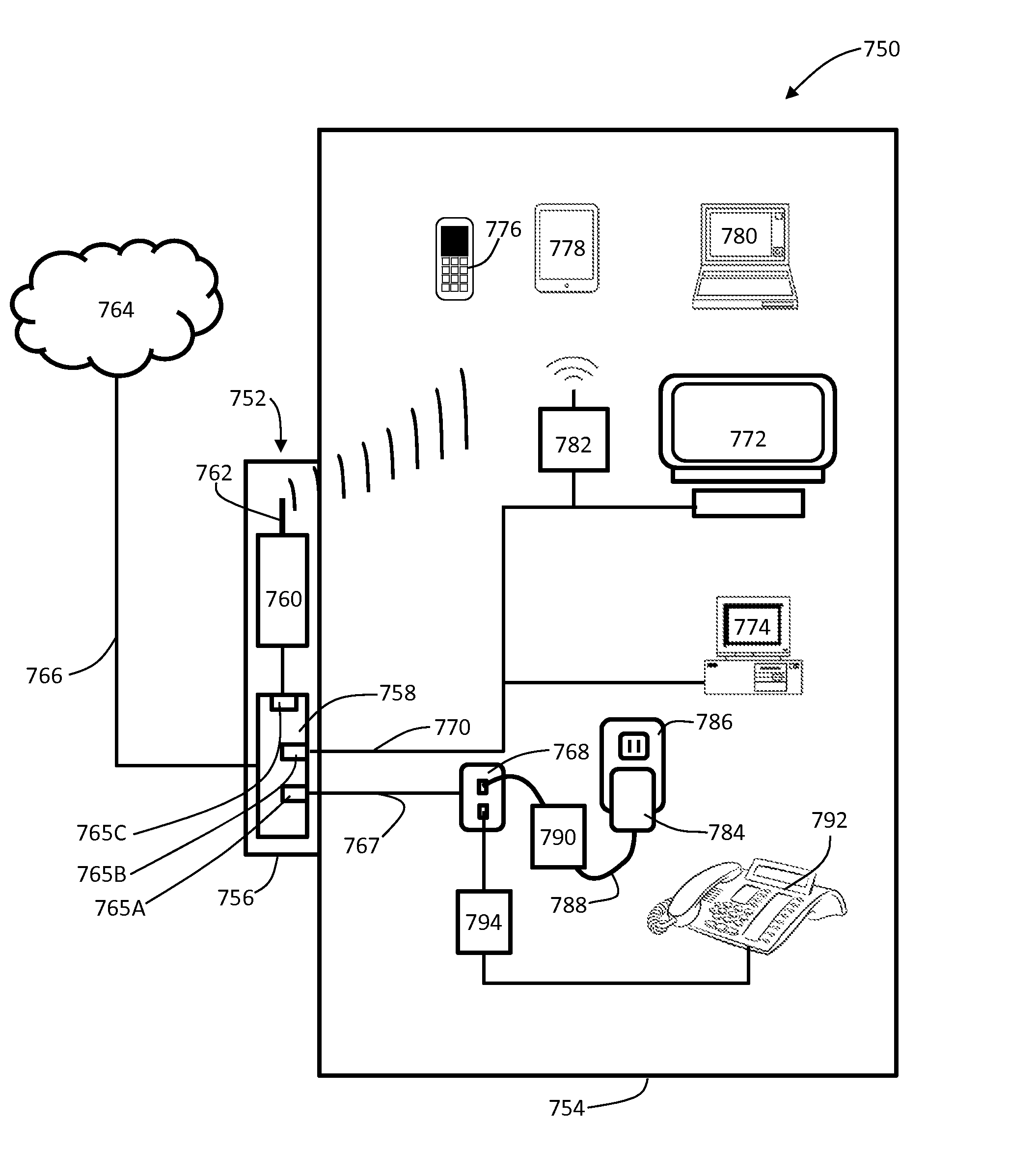
[0016]In one specific embodiment, the wireless access point and potentially other ONT elements are powered over a Category 3 telephone cable which otherwise serves to communicate telephone signals to one or more telephones within the customer premises. In this specific embodiment, the processor may include a POTS pass-through circuit providing for telephone signals received at the processor to be passively sent to the cabled telephone system within the premises whether or not the telephone cable is being used to back power a wireless access point or other ONT elements.
[0017]The system may also include a detection circuit providing for the detec

Problems solved by technology

Electrical power cannot be tra

Method used


Image

  • Antenna System and Methods for Wireless Optical Network Termination
  • Antenna System and Methods for Wireless Optical Network Termination
  • Antenna System and Methods for Wireless Optical Network Termination

Examples


Embodiment Construction

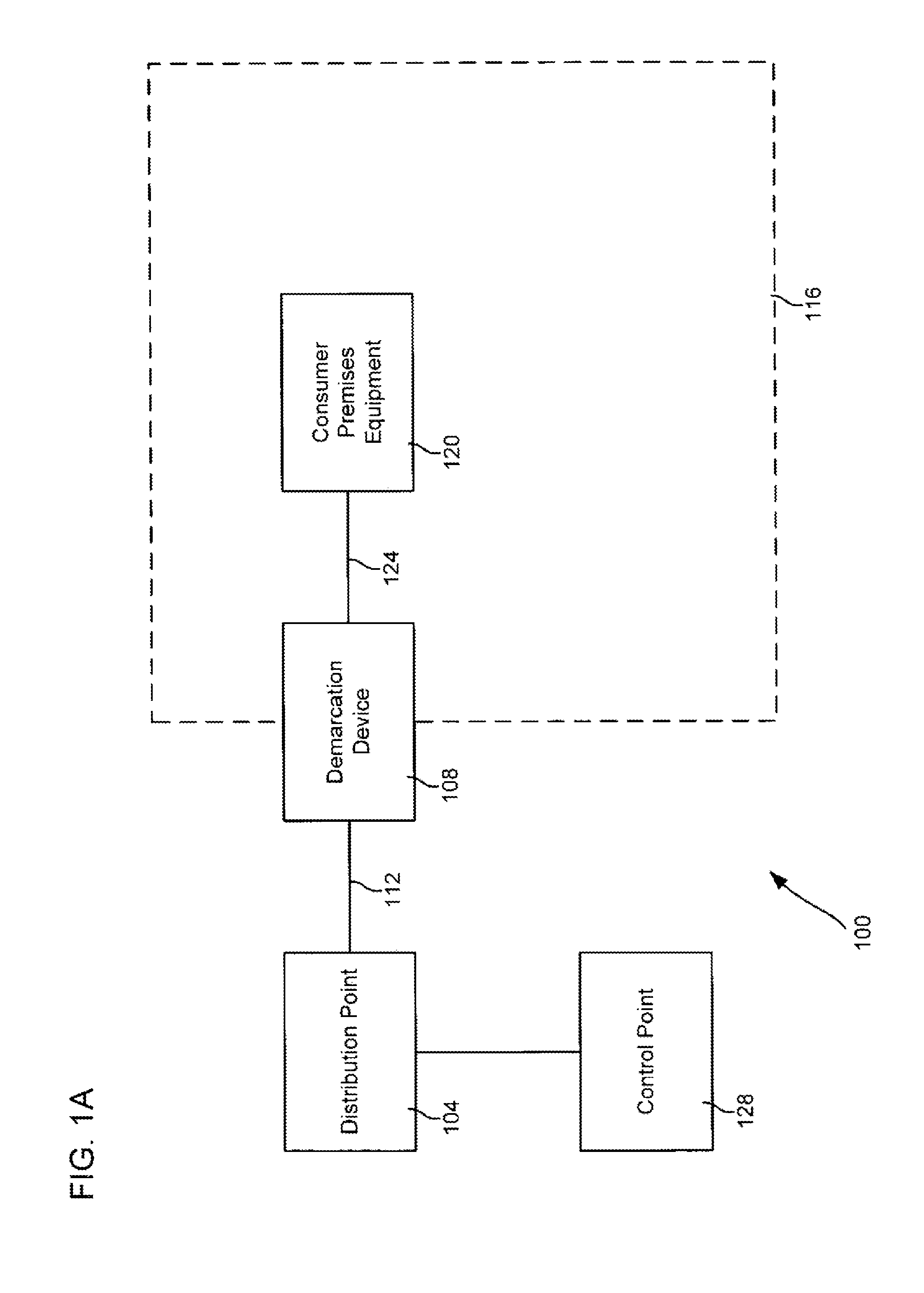
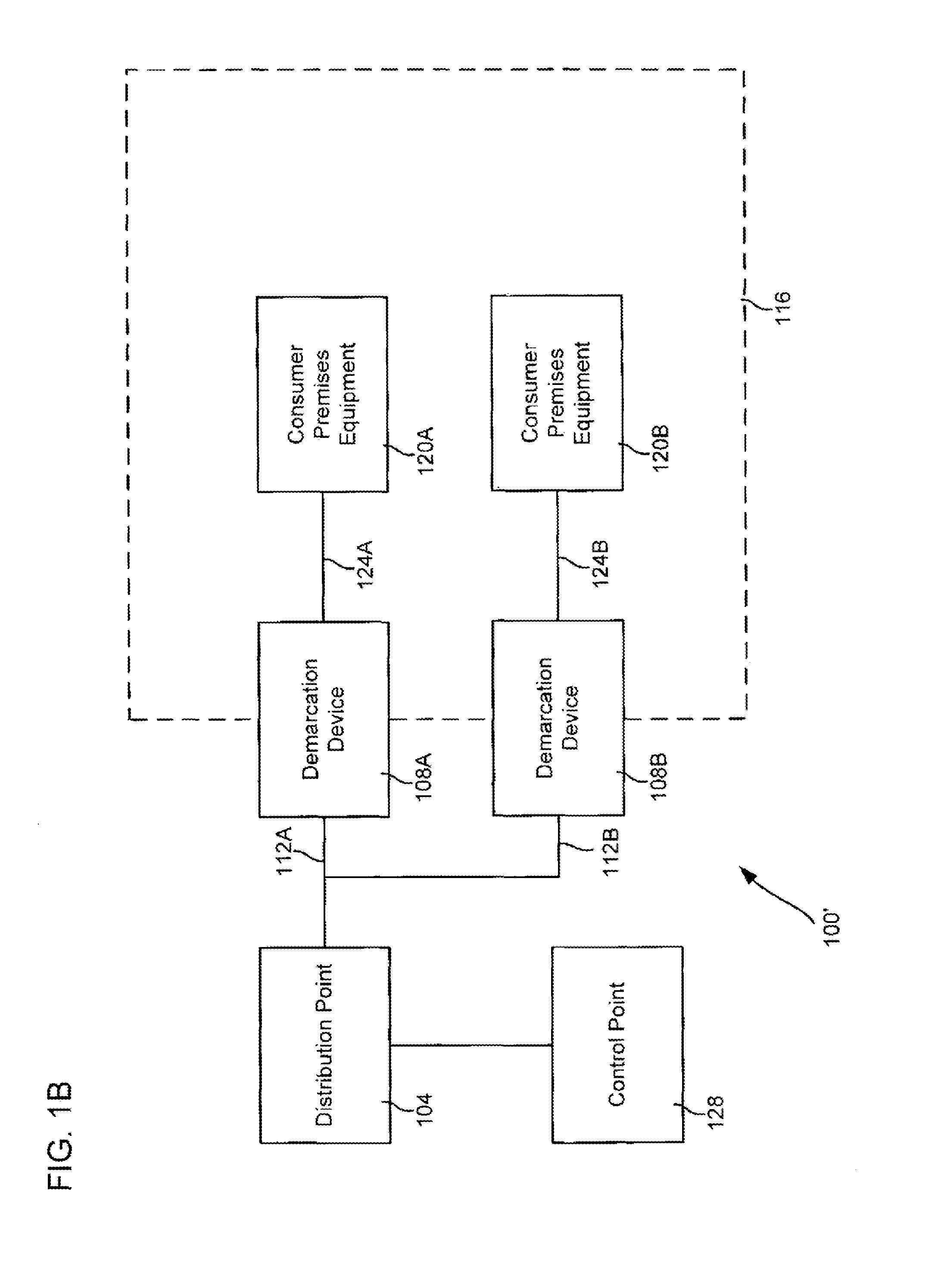
[0033]Certain embodiments of the present invention are directed to demarcation devices that can be used to provide telecommunication services, as well as to methods and systems of using such devices. A demarcation device can be any device capable of serving as an interface between a customer premises and a telecommunication service provider's network. Such devices can include, merely by way of example, set top boxes (which can be used, inter alia, as an interface between a customer's video appliance and a provider's video network), broadband modems (including xDSL modems, cable modems and wireless modems, each of which can be used to provide video and / or data to a customer premises), integrated access devices (which can, for instance, translate between Voice over IP (“VoIP”) signals and traditional telephone signals, thus allowing traditional telephones to connect to a VoIP network), devices compatible with the session initiation protocol (“SIP”) familiar to those skilled in the art...


PUM


Abstract

Optical network termination systems, devices and methods including an optical network terminal (ONT) having a processor in communication with an external optical fiber. The ONT processors further in communication with a wireless access point and at least one electrically conductive internal transport medium, both providing for the communication of telecommunication signals with devices located within a customer premises. The wireless access point and in certain instances the processor are back powered over the electrically conductive internal transport medium from AC power within the premises. In certain embodiments, the wireless access point communicates with devices within the premises over a distributed antenna.

Description

CROSS REFERENCE TO RELATED APPLICATIONS[0001]This application is a continuation-in-part of co-pending U.S. patent application Ser. No. 13 / 965,830, filed Aug. 13, 2013 by Bruce A. Phillips et al. and entitled, “Multiple-Enclosure Residential Gateways” (attorney docket no. 020370-012400US), which is a continuation of U.S. patent application Ser. No. 10 / 356,338 (now U.S. Pat. No. 8,537,814), filed Jan. 31, 2003 by Bruce A. Phillips et al. and entitled, “Configurable Network Interface Device and Systems and Methods for Its Use” (attorney docket no. 020366-090300US), both of which are hereby incorporated by reference in their entirety for all matters disclosed therein.[0002]This application may also be related to U.S. patent application Ser. No. 13 / 827,163, filed Mar. 14, 2013 by Robert J. Morrill et al. and entitled, “Multi-Service Provider Wireless Access Point” (attorney docket no. 020370-008900US), and U.S. patent application Ser. No. 13 / 541,839, filed Jul. 5, 2012 by Charles Ivan Co...

Claims


Application Information

Patent Timeline
IPC IPC(8): H04B10/2575H04B10/25
CPCH04B10/2503H04B10/25752H04L12/2834H04L63/02H04N5/45H04N7/108H04N7/22H04N21/222H04N21/234363H04N21/235H04N21/4122H04N21/4223H04N21/4316H04N21/435H04N21/43632H04N21/4622H04N21/47H04N21/4782H04N21/4886H04N21/6377H04N21/658H04N21/6587H04N2007/1739H04W88/08
Inventor COOK, CHARLES I.
Owner CENTURYLINK INTPROP
Why Eureka
Try Eureka