Firearm Suppressor Mounting Device

Inactive Publication Date: 2014-08-28
MACK ALLAN JOSEPH
View PDF32 Cites 59 Cited by
  • Summary
  • Abstract
  • Description
  • Claims
  • Application Information

AI Technical Summary

Benefits of technology

[0008]The present invention provides an improved firearm suppressor mounting device, and overcomes the above-mentioned disadvantages and drawbacks of the prior art. As such, the general purpose of the present invention, which will be described subsequently in greater detail, is to provide an improved firearm suppressor mounting device that has all the advantages of the prior art mentioned above.
[0009]To attain this, the preferred embodiment of the present invention essentially comprises a device body, a clamping element connected to the device body, a muzzle element adapted for connection to the muzzle, the muzzle element defining a first threaded portion, and the device body having a second threaded portion matable with the first threaded portion, such that the device body may be rotated and moved from an attached position and a detached position, the muzzle element having an engageme

Problems solved by technology

This has the disadvantage of being slow to mount and dismount, which is a serious concern in military and law enforcement contexts.
A loose suppressor can result in bullet strikes on the baffles because the baffles are not axially registered with the bore of the barrel.
Barrel strikes cause inaccuracy, present safety problems, and decrease equipment durability.
The use of coarser threads can improve the mounting and dismounting speed, but coarser threads are even more prone to loosening caused by the mechanical impulse of firing, as well as thermal stresses and changes du

Method used


Image

  • Firearm Suppressor Mounting Device
  • Firearm Suppressor Mounting Device
  • Firearm Suppressor Mounting Device

Examples


Embodiment Construction

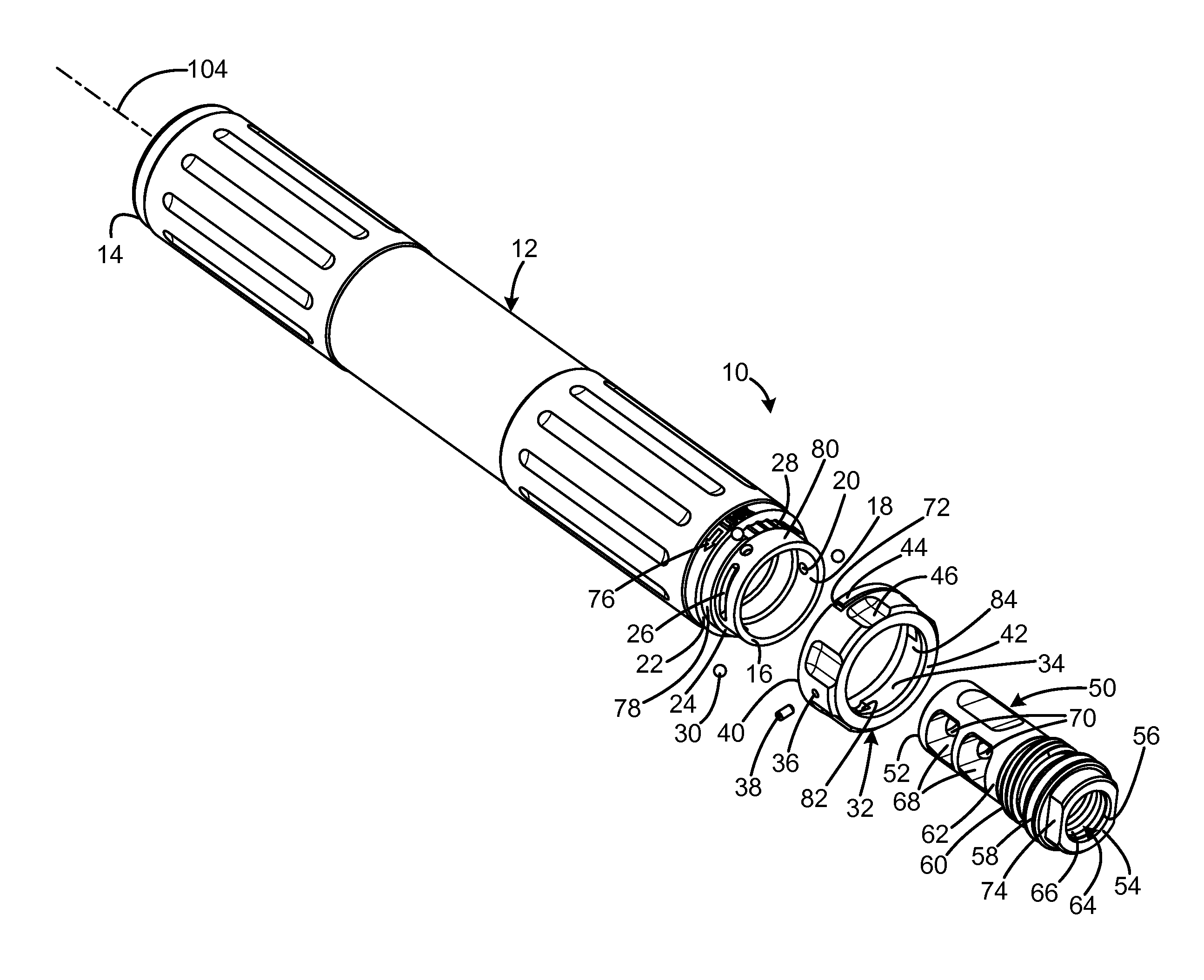
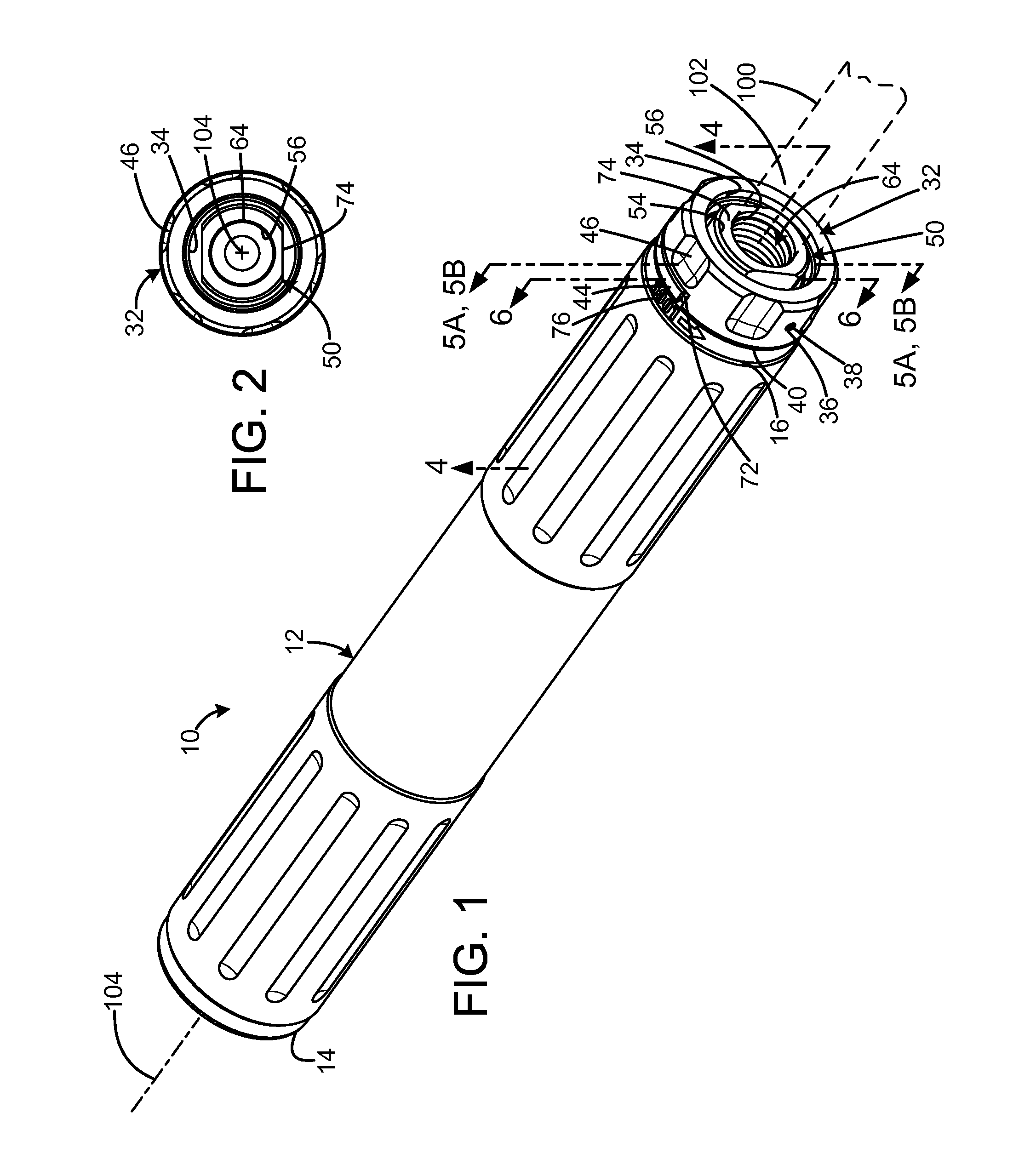
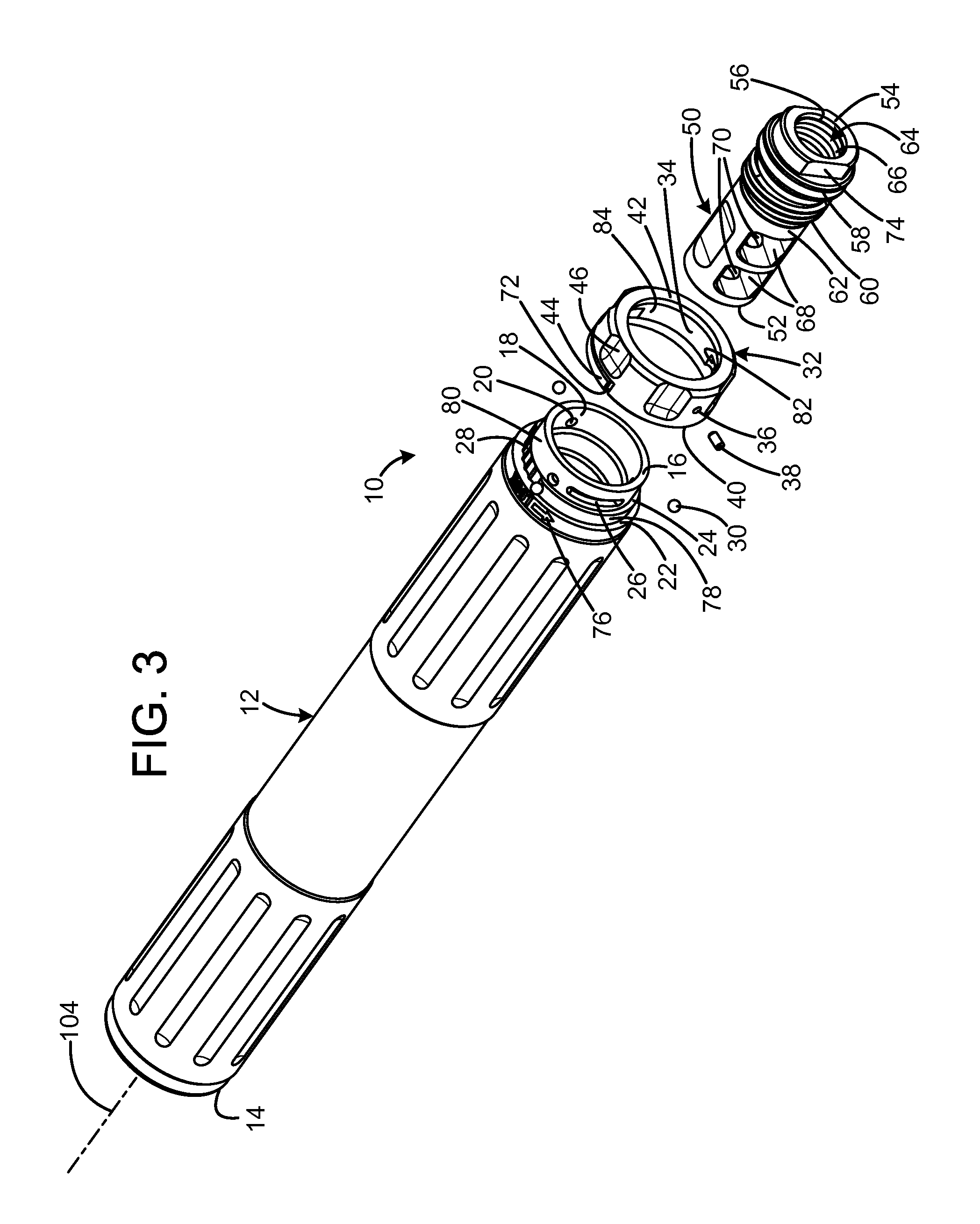
[0020]An embodiment of the firearm suppressor mounting device of the present invention is shown and generally designated by the reference numeral 10.

[0021]FIGS. 1-3 illustrate the improved firearm suppressor mounting device 10 of the present invention. More particularly, the mounting device includes a suppressor body 12, locking ring 32, and muzzle adapter 50. The body is an elongated cylindrical tube with a front 14, a rear 16, and a central bore 18. The rear of the body has a series of annular features 78, 80 having progressively smaller exterior diameters that are separated by shoulders 22, 24. The annular feature 78 includes a plurality of detents 28 on its exterior, with the remaining portion of the exterior being smooth. The annular feature 80 defines a pin slot 26 and a plurality of apertures 20 that communicate with the central bore 18. In the current embodiment, the pin slot has a length that is approximately ⅙ of the circumference of the annular feature 80, and preferably ...


PUM


Abstract

A firearm suppressor mounting device has a device body, a clamping element connected to the device body, a muzzle element adapted for connection to the muzzle, the muzzle element defining a first threaded portion, and the device body having a second threaded portion matable with the first threaded portion, such that the device body may be rotated and moved from an attached position and a detached position, the muzzle element having an engagement surface, the clamping element including at least a movable engagement element registered with the engagement surface when the device is in the attached position, and the clamping element being operably engaged to the engagement element to move it between a locked position in which the engagement element is biased against the engagement surface to prevent movement of the device to the attached position, and an unlocked position, in which detachment of the device is enabled.

Description

REFERENCE TO RELATED APPLICATION[0001]This application claims priority to U.S. Provisional Application Ser. No. 61 / 604,136 filed Feb. 28, 2012, and entitled, “RAPID ATTACH DEVICE FOR SECURING A SOUND SUPPRESSOR TO A WEAPON.”FIELD OF THE INVENTION[0002]The present invention relates to firearms, and more particularly to facilities for mounting a device on the muzzle, such as a sound suppressor.BACKGROUND OF THE INVENTION[0003]It is often desirable to mount removable devices at the muzzle of a firearm, such as a suppressor. A suppressor is a device attached to the barrel of a firearm that reduces the amount of noise and also usually the amount of muzzle flash generated by firing the weapon. A suppressor is usually a metal cylinder with internal mechanisms such as baffles to reduce the sound of firing by slowing the escaping propellant gas and sometimes by reducing the velocity of the bullet. The suppressor is typically a hollow cylindrical piece of machined metal (steel, aluminum, or t...

Claims


Application Information

Patent Timeline
IPC IPC(8): F41A21/32F41A21/34F41A21/30F41A21/36
CPCF41A21/325F41A21/36F41A21/34F41A21/30
Inventor MACK, ALLAN JOSEPH
Owner MACK ALLAN JOSEPH
Why Eureka
Try Eureka