Accelerator pedal device

Inactive Publication Date: 2014-08-28
MIKUNI CORP
View PDF4 Cites 7 Cited by
  • Summary
  • Abstract
  • Description
  • Claims
  • Application Information

AI Technical Summary

Benefits of technology

[0023]According to the accelerator pedal device having the abovementioned structure, it is possible to obtain desired hysteresis characteristics while achieving simpl

Problems solved by technology

Thus, load is applied on the pedaling force and hysteresis is generated at the pedaling force between a depression process and a return process.
Here, when such a mechanism

Method used


Image

  • Accelerator pedal device
  • Accelerator pedal device
  • Accelerator pedal device

Examples


Example

[0035]In the following, embodiments of the present invention will be described with reference to the attached drawings.

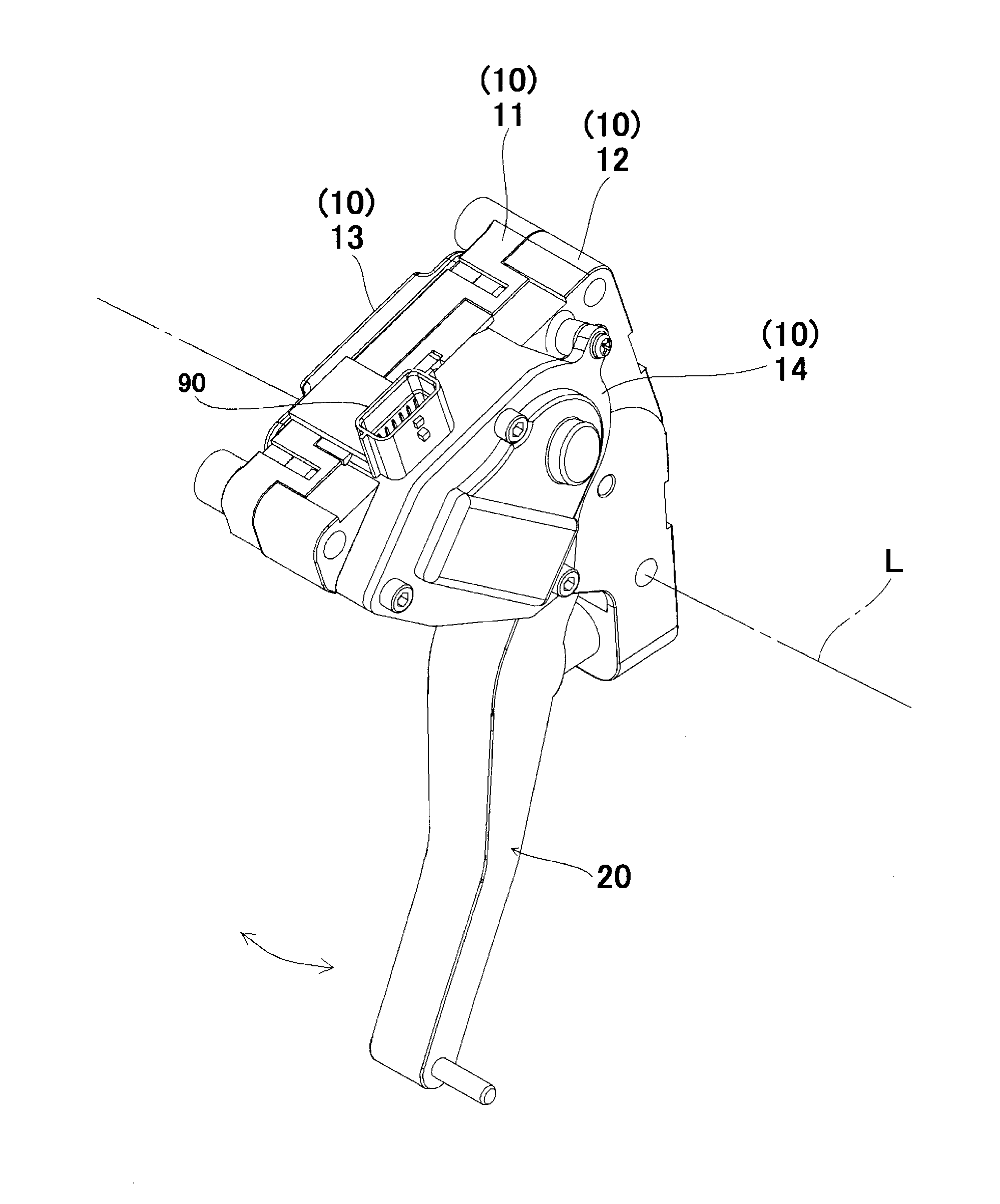
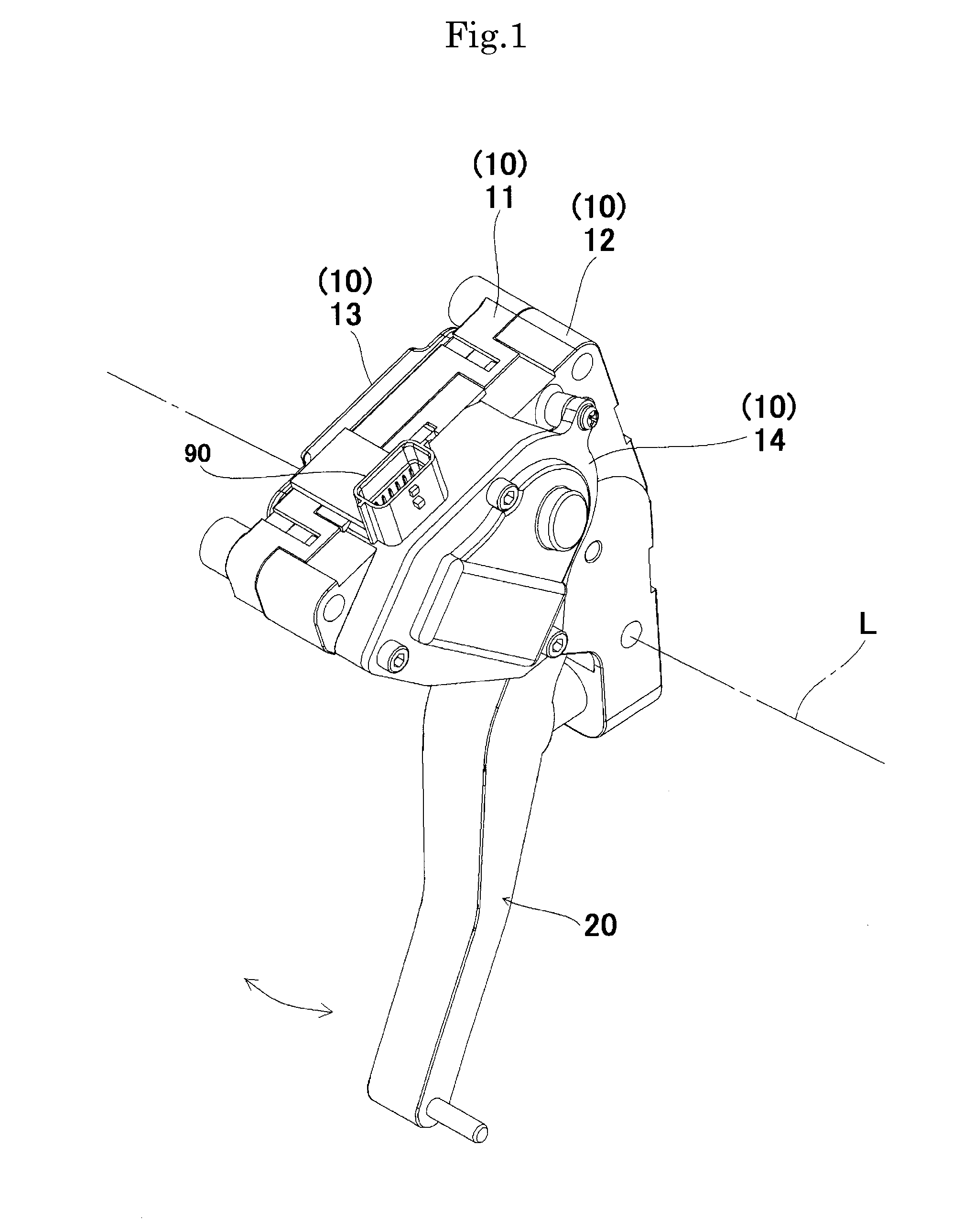
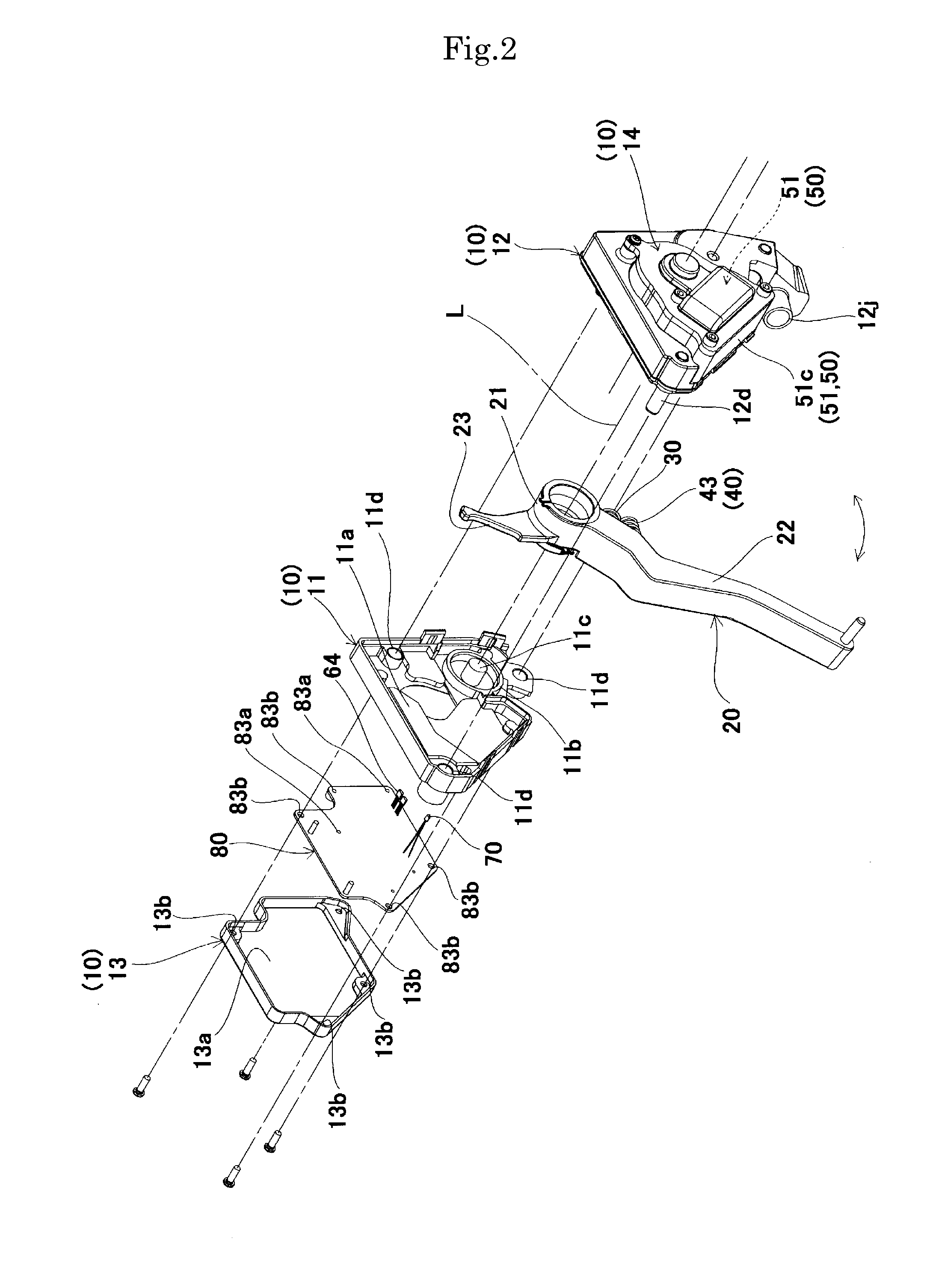
[0036]As illustrated in FIGS. 1 to 5, an accelerator pedal device includes a housing 10 which is fixed to a vehicle body of an automobile or the like, a pedal arm 20 which is pivotably supported about a predetermined axis line L defined by the housing 10 as being moved in association with an accelerator pedal (not illustrated), a return spring 30 which exerts urging force to return the pedal arm 20 to a rest position, a hysteresis generating mechanism 40 (a slide guide path 12j′, a first slider 41, a second slider 42, and an urging spring 43) which generates hysteresis at pedaling force (pedaling load) of the accelerator pedal, an active control mechanism 50 (a drive source 51 (a rotor 51a, a coil 51b, and a yoke 51c), and a return lever 52) which generates push-back force to push back the pedal arm 20 toward the rest position under predetermined conditions, a posit...


PUM


Abstract

An accelerator pedal device includes a slide guide path which is formed in a housing, a first slider which is engaged with the pedal arm for receiving pedaling force as being slidably arranged in the slide guide path and which includes a first inclined face inclined against a movement direction of the first slider, a second slider which is slidably arranged in the slide guide path and which includes a second inclined face contacted to the first inclined face, and an urging spring which exerts urging force in a direction opposing to the pedaling force as being engaged with the second slider, wherein the slide guide path is formed as being tapered in a direction of movement of the first slider and the second slider which are moved in association with depression of the accelerator pedal. Accordingly, desired hysteresis can be obtained on the pedaling force while achieving downsizing.

Description

TECHNICAL FIELD[0001]The present invention relates to an accelerator pedal device applied to a vehicle of the like, and in particular, relates to an accelerator pedal device applied to a vehicle or the like having a drive-by-wire system.BACKGROUND ART[0002]There has been conventionally known an accelerator pedal device including a housing (support case) which is fixed to a vehicle body of an automobile or the like, a pedal arm (accelerator arm) which is swingably supported by the housing as integrally including an accelerator pedal, a return spring which returns the pedal arm to a rest position, a hysteresis generating mechanism which generates hysteresis at pedaling force (pedaling load), an accelerator sensor which detects a rotational amount of the pedal arm as accelerator opening, and the like. Here, the hysteresis generating mechanism includes two frictional pieces (a frictional piece and a subsidiary frictional piece) with inclined faces thereof mutually contacted to provide a...

Claims


Application Information

Patent Timeline
IPC IPC(8): G05G1/44
CPCG05G1/44F02D11/02B60K26/021B60K2026/023F02D11/04Y10T74/20534
Inventor KASHIYAMA, MEGURUKUMAMOTO, MASATO
Owner MIKUNI CORP
Why Eureka
Try Eureka