Method Of Locating An Event Transmitting A Signal
- Summary
- Abstract
- Description
- Claims
- Application Information
AI Technical Summary
Benefits of technology
Problems solved by technology
Method used
Image

Examples
Embodiment Construction
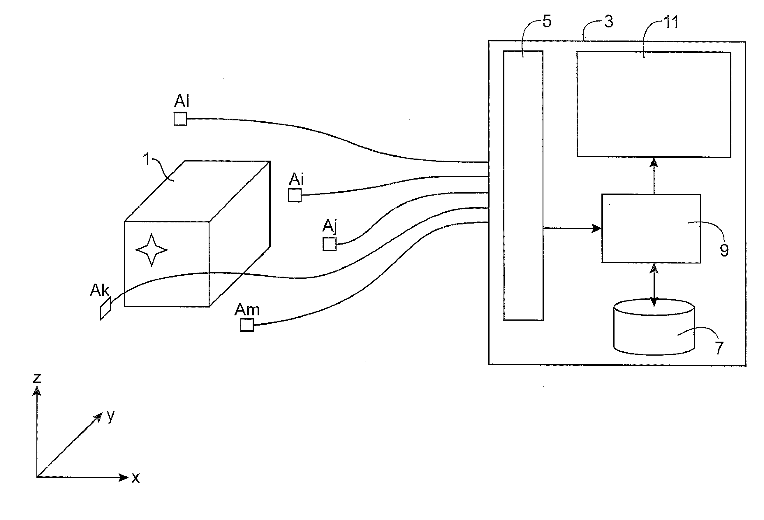
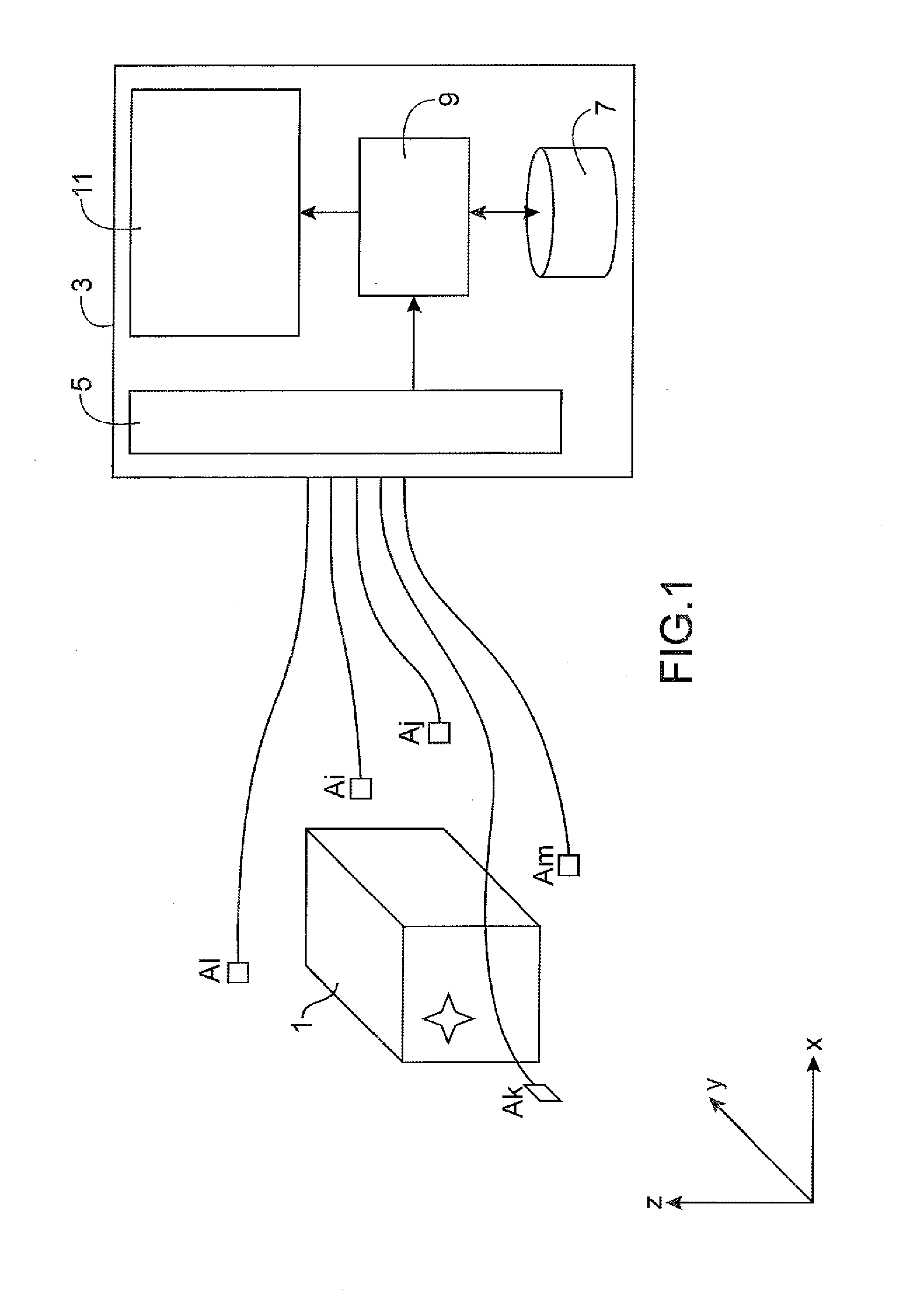
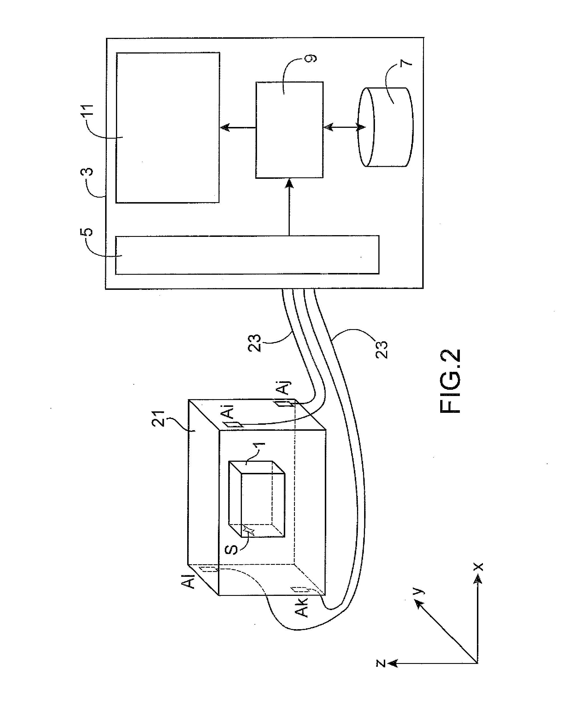
[0008]The present invention is defined by a method for locating an event transmitting a signal, including a measurement of the response times of the said signal by a set of sensors, and a solution of a system of equations defining distances between the said sensors and the said event as a function of a speed of propagation of the said signal and of an offset of the said response times relative to a reference time. If the system of equations has no solution indicating the position of the event the method includes the following steps:[0009]recommencing several times the solution of the system of equations, by modifying with each iteration the response time of at least one of the said sensors, applying an increase or a reduction of the said response time by a percentage of less than a determined value, where the solution of the said system of equations is recommenced with each iteration, until the sum for each of the sensors, of the different increases or reductions of the said respons...
PUM
 Abstract
Description
Claims
Application Information
 - R&D
- Intellectual Property
- Life Sciences
- Materials
- Tech Scout
- Unparalleled Data Quality
- Higher Quality Content
- 60% Fewer Hallucinations
Browse by: Latest US Patents, China's latest patents, Technical Efficacy Thesaurus, Application Domain, Technology Topic, Popular Technical Reports.
© 2025 PatSnap. All rights reserved.Legal|Privacy policy|Modern Slavery Act Transparency Statement|Sitemap|About US| Contact US: help@patsnap.com