Methods and system for real-time cardiac mapping

a real-time cardiac mapping and method technology, applied in the field of cardiac mapping technology, can solve the problems of inconvenient and time-consuming process of creating an electroanatomic map, inconvenient use, and inability to accurately predict the pathologic tachyarrhythmia,

Inactive Publication Date: 2014-08-28
AMERICAN MEDICAL TECH LLC
View PDF1 Cites 28 Cited by
  • Summary
  • Abstract
  • Description
  • Claims
  • Application Information

AI Technical Summary

Benefits of technology

The present invention introduces new ways to map out the heart's electrical activity and treat irregular heart rhythms. This can help with identifying and eliminating areas that cause these issues.

Problems solved by technology

The technical problem addressed in this patent text is the development of a new mapping system for the heart that is direct, affordable, and easy to operate. Current mapping systems are indirect, expensive, and difficult to manage. This new system should allow for real-time tracking of the catheter during procedures without requiring continuous fluoroscopy.

Method used


Image

  • Methods and system for real-time cardiac mapping
  • Methods and system for real-time cardiac mapping
  • Methods and system for real-time cardiac mapping

Examples


Embodiment Construction

[0112]The following description is of the best mode presently contemplated for carrying out the disclosure. This description is not to be taken in a limiting sense, but is made merely for the purpose of describing the general principles of the disclosure. The scope of the disclosure should be determined with reference to the claims.

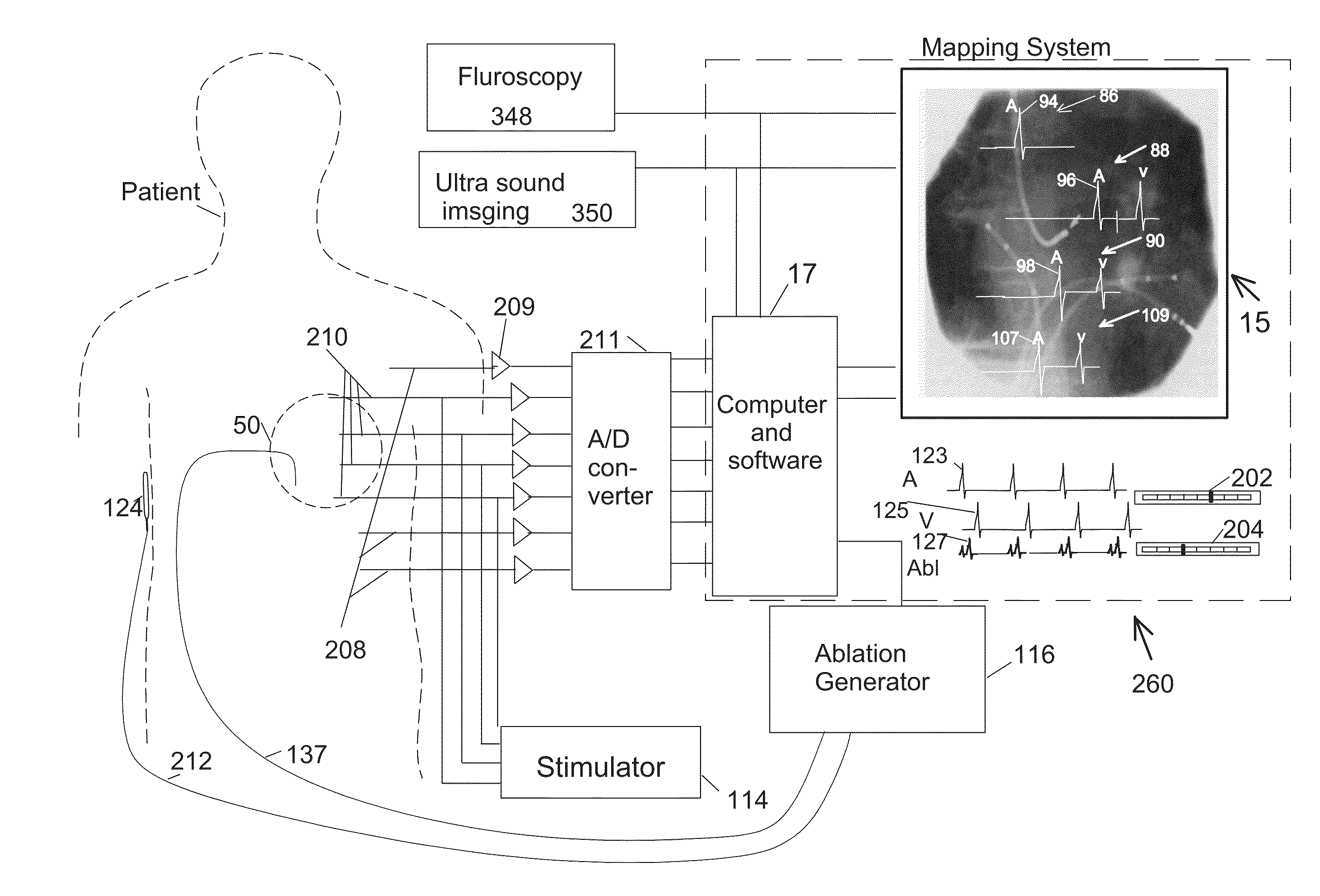
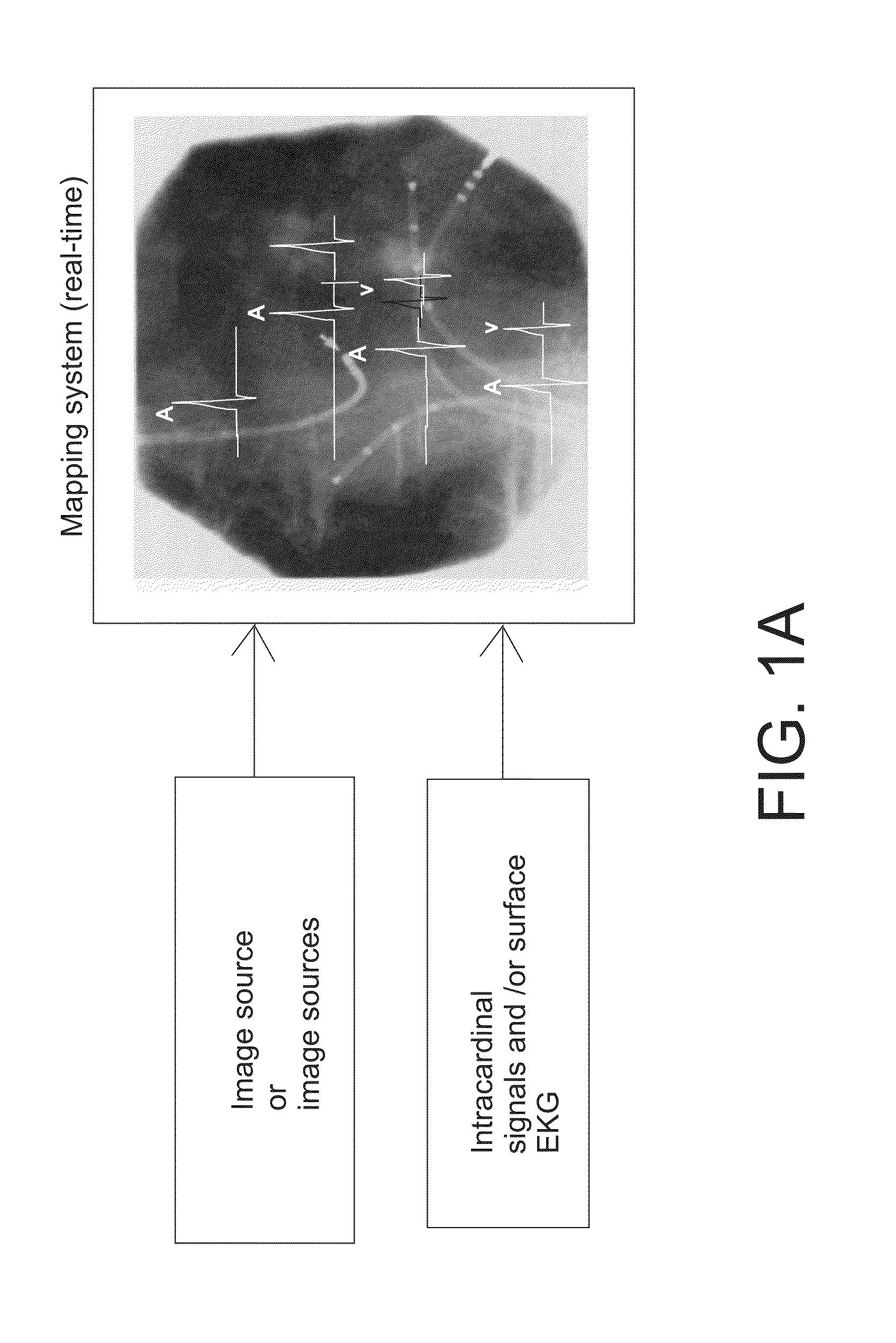
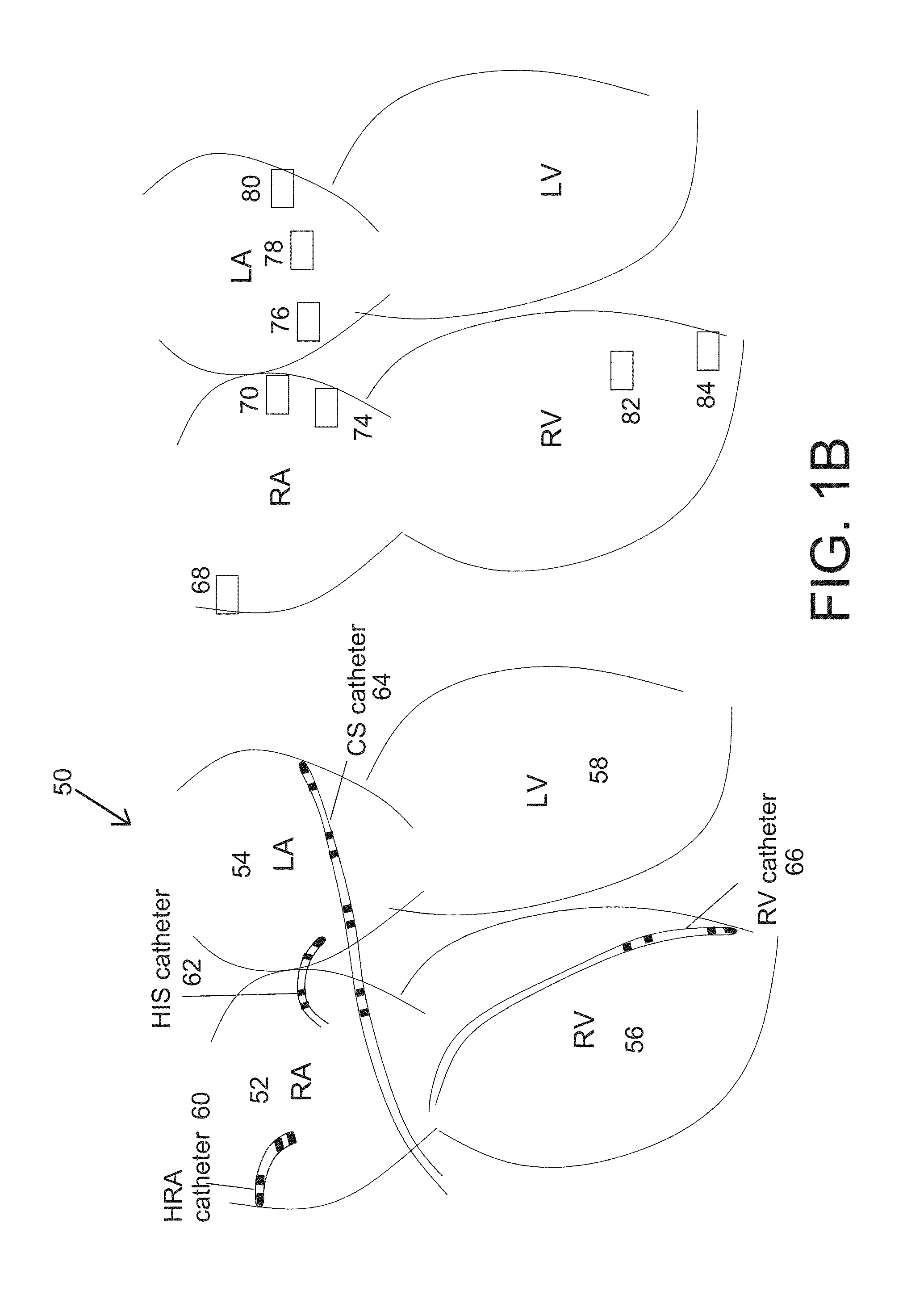
[0113]In the cardiac electrophysiology art, electroanatomical mapping generally refers to superimposing of the electrical activity on an image or computer model of the heart. Patient's electrical timing information is generally color coded on a computer model. Prior art electroanatomical systems (Biosense Websters's Carto™ system and St Jude Medical's Navix™ system), generally collect information point by point, with the physician manipulating the mapping catheter within a chamber of the heart. The points are then captured on the computer by an operator. Each point contains location or geometry information as well as electrical timing information relative...


PUM


Abstract

A method and system of electroanatomical mapping comprises bringing a patient's image such as a fluoroscopic image and intracardiac signals into a computer based mapping system. Electroanatomical mapping or superimposing of cardiac electrical activity on fluoroscopic image is provided by placing visual indicators on electrode pairs of various catheters including standard catheters and ablation catheter. Visual indicators are coupled or linked to underlying electric signals from those electrode pairs via software coding, whereby electrical activity sequence of the heart is provided and updated in real-time on fluoroscopic image. A combination of fluoroscopic image and CT or MRI may also be used. The mapping system further comprises various algorithms for aiding in cardiac mapping and ablation of cardiac arrhythmias.

Description


Claims


Application Information

Patent Timeline
Owner AMERICAN MEDICAL TECH LLC
Why Eureka
Try Eureka