System and method for reducing combustion dynamics

a combustion dynamics and combustion technology, applied in the field of system and method for reducing combustion dynamics, can solve the problems of accelerating the wear of the fuel nozzle in a relatively short amount of time, and increasing the production of carbon monoxide and unburned hydrocarbons. , to achieve the effect of reducing combustion dynamics

Active Publication Date: 2014-09-04
GENERAL ELECTRIC CO
View PDF3 Cites 30 Cited by
  • Summary
  • Abstract
  • Description
  • Claims
  • Application Information

AI Technical Summary

Benefits of technology

[0006]One embodiment of the present invention is a system for reducing combustion dynamics that includes first and second combustors arranged about an axis, and each combustor includes a plurality of tubes that extend axially through at least a portion of the combustor and a combustion chamber downstream from the plurality of tubes. A fuel injector extends through each tube to provide fluid communication into each tube at a fourth axial distance from the combustion chamber. The fourth axial distance in the first combustor is different than the fourth axial distance in the second combustor.

Problems solved by technology

However, higher combustion gas temperatures also promote flame holding conditions in which the combustion flame migrates toward the fuel being supplied by the fuel nozzles, possibly causing accelerated wear to the fuel nozzles in a relatively short amount of time.
Conversely, a lower combustion gas temperature associated with reduced fuel flow and / or part load operation (turndown) generally reduces the chemical reaction rates of the combustion gases, increasing the production of carbon monoxide and unburned hydrocarbons.
Although effective at enabling higher operating temperatures while protecting against flame holding and controlling undesirable emissions, at particular operating conditions, some combustors may produce combustion instabilities that result from an interaction or coupling of the combustion process or flame dynamics with one or more acoustic resonant frequencies of the combustor.
The result is combustion dynamics that may reduce the useful life of one or more combustor and / or downstream components.
For example, the combustion dynamics may produce pressure pulses inside the fuel nozzles and / or combustion chambers that may adversely affect the high cycle fatigue life of these components, the stability of the combustion flame, the design margins for flame holding, and / or undesirable emissions.
Alternately, or in addition, combustion dynamics at specific frequencies and with sufficient amplitudes, that are in-phase and coherent, may produce undesirable sympathetic vibrations in the turbine and / or other downstream components.
This reduces the ability of the combustor tone to cause a vibratory response in downstream components and also encourages destructive interference from combustor-to-combustor, reducing combustion dynamics amplitudes.

Method used


Image

  • System and method for reducing combustion dynamics
  • System and method for reducing combustion dynamics
  • System and method for reducing combustion dynamics

Examples


first embodiment

[0033]The combustion dynamics associated with multiple combustors 14 incorporated into the gas turbine 10 may in turn either constructively or destructively interfere with one another to increase or decrease the amplitude and / or coherence of the combustion dynamics associated with the gas turbine 10. In particular embodiments, the combustion instability frequencies and / or combustion dynamics associated with one or more combustors 14 may be adjusted and / or tuned to affect the interaction with the combustion dynamics of another combustor 14 and thus the combustion dynamics associated with the gas turbine 10. For example, FIG. 7 provides a system for reducing combustion dynamics and / or coherence of the combustion dynamics according to the present invention. In the particular embodiment shown in FIG. 7, multiple combustors 14 as shown in FIGS. 3 and 6 have been arranged about an axis 78. The axis 78 may coincide, for example, with the rotor 18 in the gas turbine 10 that connects the com...

second embodiment

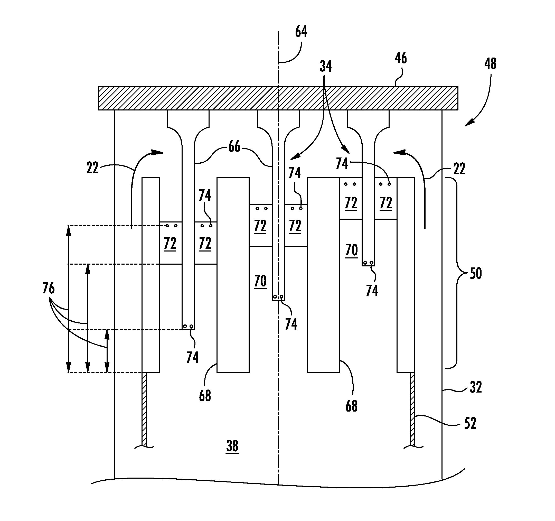
[0035]FIG. 8 provides a system for reducing combustion dynamics according to the present invention. As shown in FIG. 8, each combustor 14 again includes multiple fuel nozzles 34 with the combustion chamber 38 downstream from the fuel nozzles 34 as previously described with respect to FIGS. 2, 3, 6 and 7. In addition, the axial positions of the fuel ports 74 and / or the vanes 72 may be the same or different in each combustor 14. In the specific embodiment shown in FIG. 8, for example, the axial positions of the fuel ports 74 and the vanes 72 are different within the same combustor 14, but the axial positions of the fuel ports 74 and the vanes 72 are repeated in both of the combustors 14.

[0036]The embodiment shown in FIG. 8 again includes means for producing a combustion instability frequency or resonant frequency in one combustor 14 that is different from the combustion instability frequency or resonant frequency in the other combustor 14. In this particular embodiment, the structure ...

third embodiment

[0042]The combustion dynamics associated with multiple combustors 14 incorporated into the gas turbine 10 may in turn either constructively or destructively interfere with one another to increase or decrease the amplitude and / or coherence of the combustion dynamics associated with the gas turbine 10. In particular embodiments, the combustion instability frequencies and / or combustion dynamics associated with one or more combustors 14 may be adjusted and / or tuned to affect the interaction with the combustion dynamics of another combustor 14 and thus the combustion dynamics associated with the gas turbine 10. For example, FIG. 10 provides a system for reducing combustion dynamics according to the present invention. In the particular embodiment shown in FIG. 10, multiple combustors 14 as shown in FIGS. 5 and 9 have been arranged about an axis 100. The axis 100 may coincide, for example, with the rotor 18 in the gas turbine 10 that connects the compressor section 12 to the turbine sectio...


PUM


Abstract

A system and method for reducing combustion dynamics includes first and second combustors arranged about an axis, and each combustor includes a plurality of tubes that extend axially through at least a portion of the combustor and a combustion chamber downstream from the plurality of tubes. A fuel injector extends through each tube to provide fluid communication into each tube at a fourth axial distance from the combustion chamber. The fourth axial distance in the first combustor is different than the fourth axial distance in the second combustor.

Description

FIELD OF THE INVENTION[0001]The present invention generally involves a system and method for reducing combustion dynamics. In particular embodiments, the invention may be incorporated into a gas turbine or other turbo-machine.BACKGROUND OF THE INVENTION[0002]Combustors are commonly used in industrial and commercial operations to ignite fuel to produce combustion gases having a high temperature and pressure. For example, gas turbines and other turbo-machines typically include one or more combustors to generate power or thrust. A typical gas turbine used to generate electrical power includes an axial compressor at the front, multiple combustors around the middle, and a turbine at the rear. Ambient air enters the compressor as a working fluid, and the compressor progressively imparts kinetic energy to the working fluid to produce a compressed working fluid at a highly energized state. The compressed working fluid exits the compressor and flows through one or more fuel nozzles and / or tu...

Claims


Application Information

Patent Timeline
Patent Type & Authority Applications(United States)
IPC IPC(8): F02C7/24
CPCF02C7/24F02C7/228F23R3/286F23R3/34F23R2900/00014F23R3/18F23R3/42F02C7/22F23D14/02F23R3/20F23R3/283F23R3/46
Inventor CROTHERS, SARAH LORIKRAEMER, GILBERT OTTO
Owner GENERAL ELECTRIC CO
Why Eureka
Try Eureka