Rops mount for work vehicle display interface

a technology for display interfaces and work vehicles, applied in vehicle components, off-road vehicles, supplementary fittings, etc., can solve the problems of insufficient front and rear implements, display interfaces providing information of this sort that may be vital to the operation of the vehicle, and the inability to mount the display to the seat armrest, etc., to achieve the effect of adjusting the display interfa

Inactive Publication Date: 2014-09-04
DEERE & CO
View PDF9 Cites 52 Cited by
  • Summary
  • Abstract
  • Description
  • Claims
  • Application Information

AI Technical Summary

Benefits of technology

[0008]An adjustable mounting assembly capable of mounting a display interface to the ROPS of a work vehicle that has two operational sides, for example the front and rear sides of the vehicle having the work implements, such as the front loader and rear excavator of a backhoe. The adjustable mounting assembly can include a linear translation mechanism and rotating dock to allow the vehicle operator to readily adjust the display interface so that it is viewable in both the front and rear facing seating orientations of the vehicle.

Problems solved by technology

Space within the vehicle cabin of such work vehicles is typically limited.
Static mounting in a conventional instrument dashboard panel such display interfaces providing information of this sort that may be vital to the operation of the vehicle and both front and rear implements is insufficient.
However, mounting the display to the seat armrest is often not possible because there is insufficient room in the cabin for the seat to rotate without the linkage or display interfering with other components, or when mounted to the cab floor without the linkage or display being an impediment for the seat to rotate.
Even if there is sufficient space, typically the operator must manipulate such linkage arrangements significantly to orient the display in the desired positions, thereby causing difficult or imprecise positioning of the display and diminishing the operator experience in the vehicle.

Method used


Image

  • Rops mount for work vehicle display interface
  • Rops mount for work vehicle display interface
  • Rops mount for work vehicle display interface

Examples


Embodiment Construction

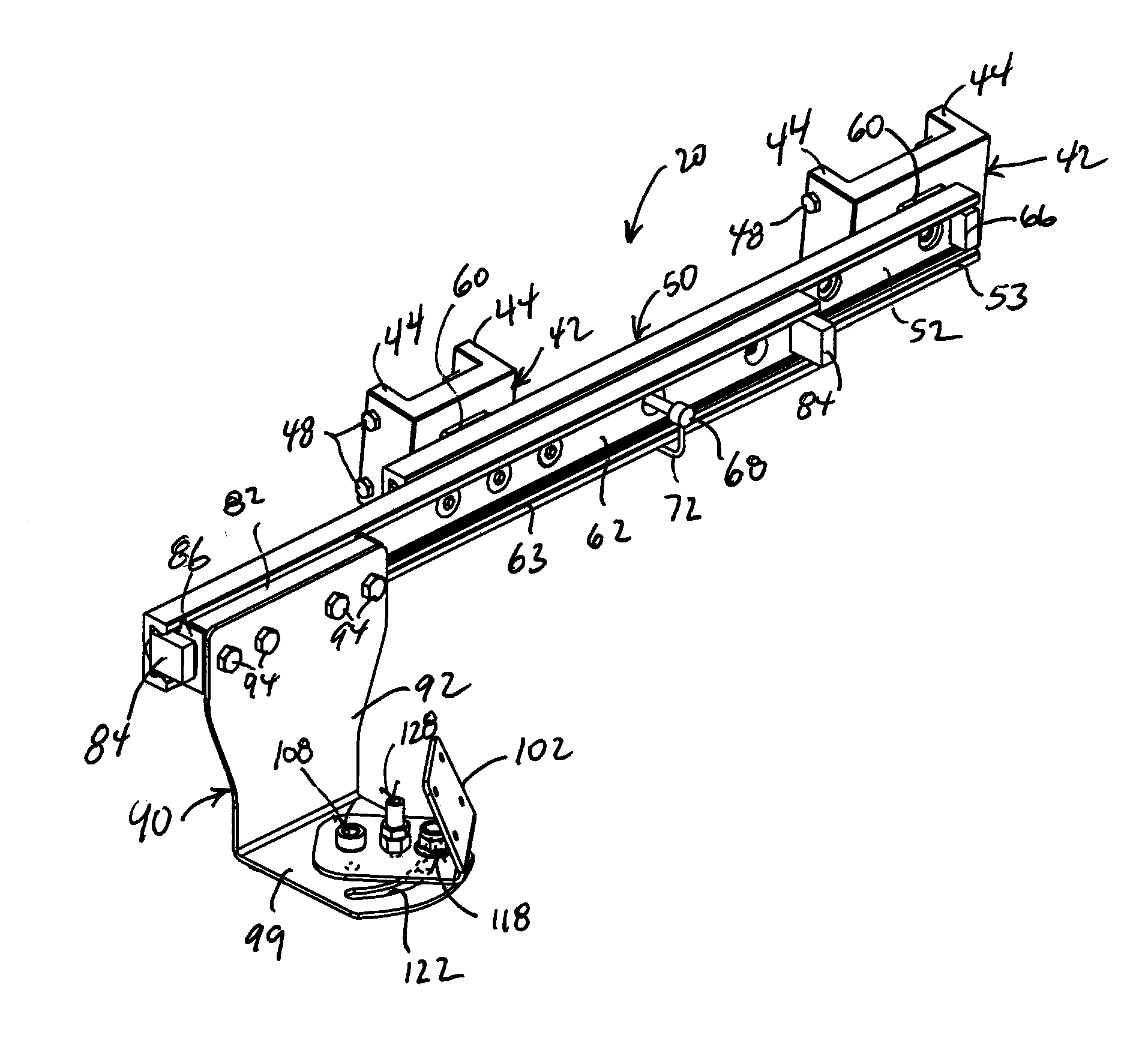
[0033]As shown in the accompanying figures of the drawings described above, the following describes one or more example constructions of an adjustable mounting assembly, which can be used to mount an operator control interface display within the operator compartment of a work vehicle. Various modifications to the example construction(s) may be contemplated by one of skill in the art.

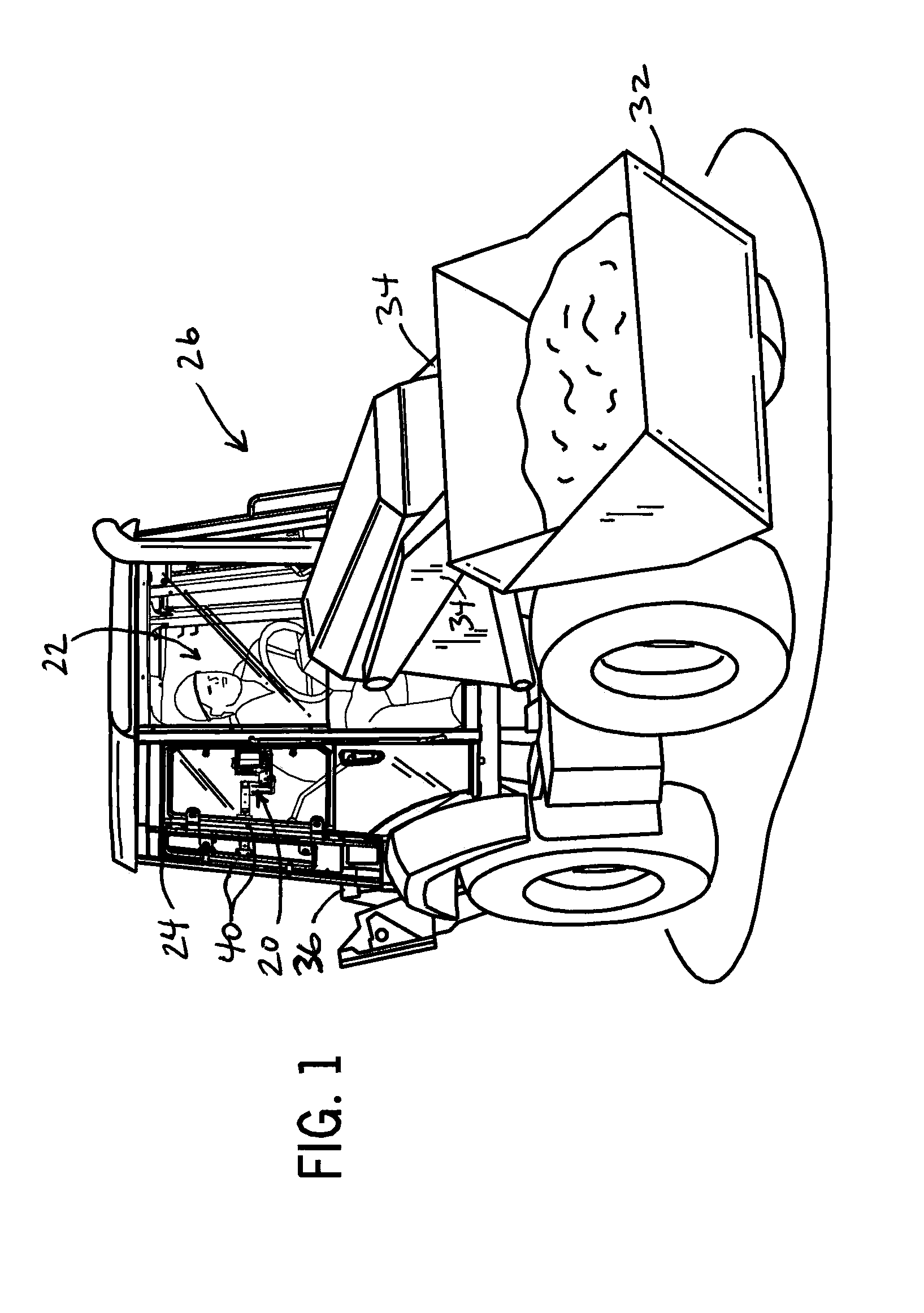
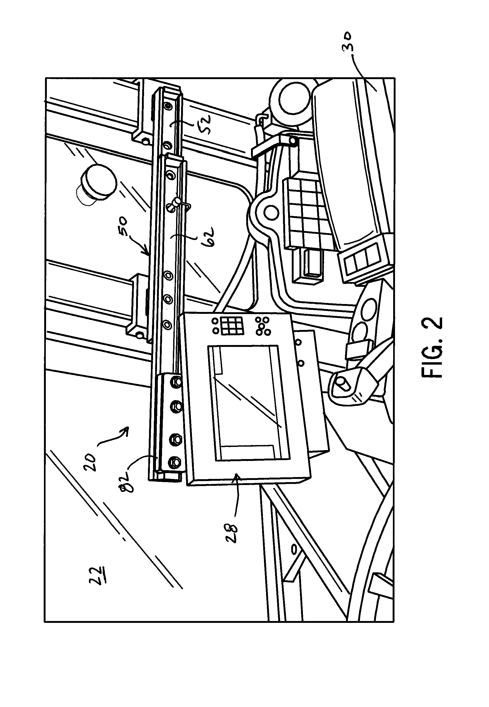
[0034]FIG. 1 shows an example application of a mounting assembly 20 incorporated into the operator compartment 22 within the cabin 24 of a work vehicle 26. As shown in FIGS. 2-5, the mounting assembly 20 can be used to mount and adjust the position and orientation of a display interface 28. As will be described in detail, the mounting assembly 20 can readily reposition the display interface 28 in the position and orientation required for the operator to view the display interface 28 when the operator seat 30 faces the front of the work vehicle 26 or is rotated to face the rear of the work vehicle 26. The...


PUM


Abstract

An adjustable mounting assembly capable of mounting an operator display interface to the ROPS of a work vehicle that has front and rear implements, such as the front loader and rear excavator of a backhoe. The adjustable mounting assembly can have a telescoping compound slide assembly with at least one movable rail and slider. The moveable rail and slider can translate to move a display mount linearly between the front or rear of the vehicle. A display bracket can rotate about a generally vertical axis. Detents or other positioning elements can be provided on the rails and slider as well as at preset angular orientations of the display mount. The adjustable mounting assembly thus allows the vehicle operator to readily adjust the display interface to be viewable when in the front and rear facing seating orientations of the vehicle.

Description

CROSS-REFERENCE TO RELATED APPLICATION(S)[0001]Not applicable.STATEMENT OF FEDERALLY SPONSORED RESEARCH OR DEVELOPMENT[0002]Not applicable.FIELD OF THE DISCLOSURE[0003]This disclosure relates to work vehicles, and in particular to a mechanism for adjustably mounting a display interface so it can be viewed by the vehicle operator in multiple primary seating positions.BACKGROUND OF THE DISCLOSURE[0004]Various work vehicles have work implements at both the front and rear of the vehicle. To permit the vehicle operator to view and control the working implement, the operator seat can rotate to face either the front or rear of the vehicle. For example, in a backhoe, the seat is positioned so that the operator faces forward when driving the vehicle and operating the front loader bucket and faces rearward when operating the rear excavator arm.[0005]Space within the vehicle cabin of such work vehicles is typically limited. The available space problem has become an increasing concern in light ...

Claims


Application Information

Patent Timeline
Patent Type & Authority Applications(United States)
IPC IPC(8): B60R11/02
CPCB60R11/0229B60R2011/008B60K35/00B60Y2200/20B60K2370/67B60K2370/81B60K2370/61B60K37/02B60R11/0235B60R2011/0084
Inventor MONTGOMERY, JAMES L.LAHEY, JASON C.CUFR, RANDY A.
Owner DEERE & CO
Why Eureka
Try Eureka