Fan speed testing device

a testing device and fan speed technology, applied in the direction of mechanical equipment, machines/engines, instruments, etc., can solve the problems of inefficient heat dissipation of heat emitted by some electronic components, cpus may generate a lot of heat, and the rotation speed may not reach a certain rotation speed,

Inactive Publication Date: 2014-09-04
HONG FU JIN PRECISION IND (SHENZHEN) CO LTD +1
View PDF16 Cites 7 Cited by
  • Summary
  • Abstract
  • Description
  • Claims
  • Application Information

AI Technical Summary

Problems solved by technology

During operation of computers, for example, some electronic components, such as CPUs, may generate a lot of heat.
However, depending on the type, manufacturer, and usage time of the fan, the rotation speed may not reach one certain rotation speed when the same PWM signals are sent to different fans.
Thus, the heat emitted by some electronic components may not be dissipated efficiently, which may cause the electronic device to burn out.

Method used


Image

  • Fan speed testing device
  • Fan speed testing device
  • Fan speed testing device

Examples


Embodiment Construction

[0014]The disclosure is illustrated by way of example and not by way of limitation in the figures of the accompanying drawings in which like references indicate similar elements. It should be noted that references to “an” or “one” embodiment in this disclosure are not necessarily to the same embodiment, and such references mean “at least one.”

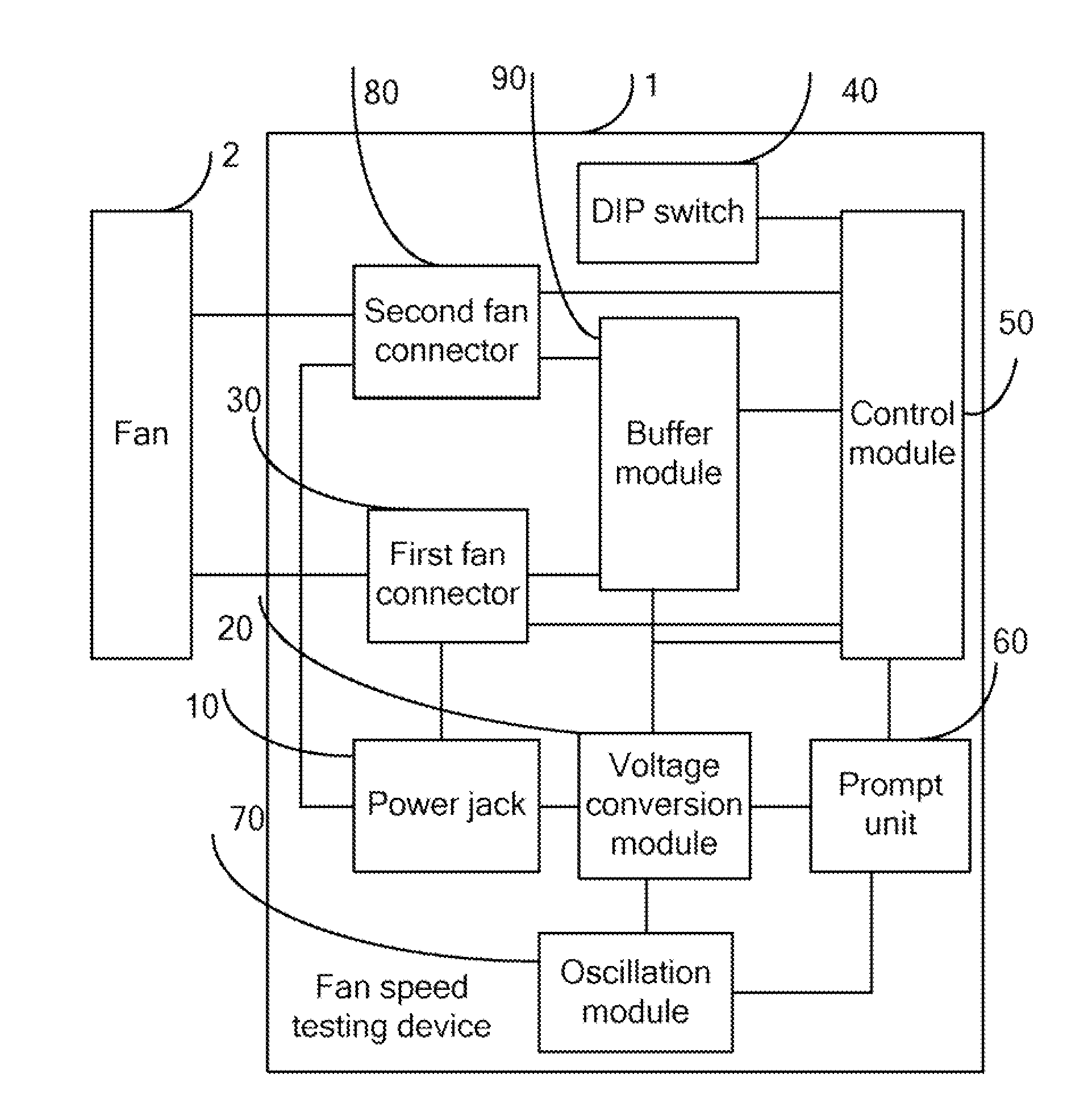
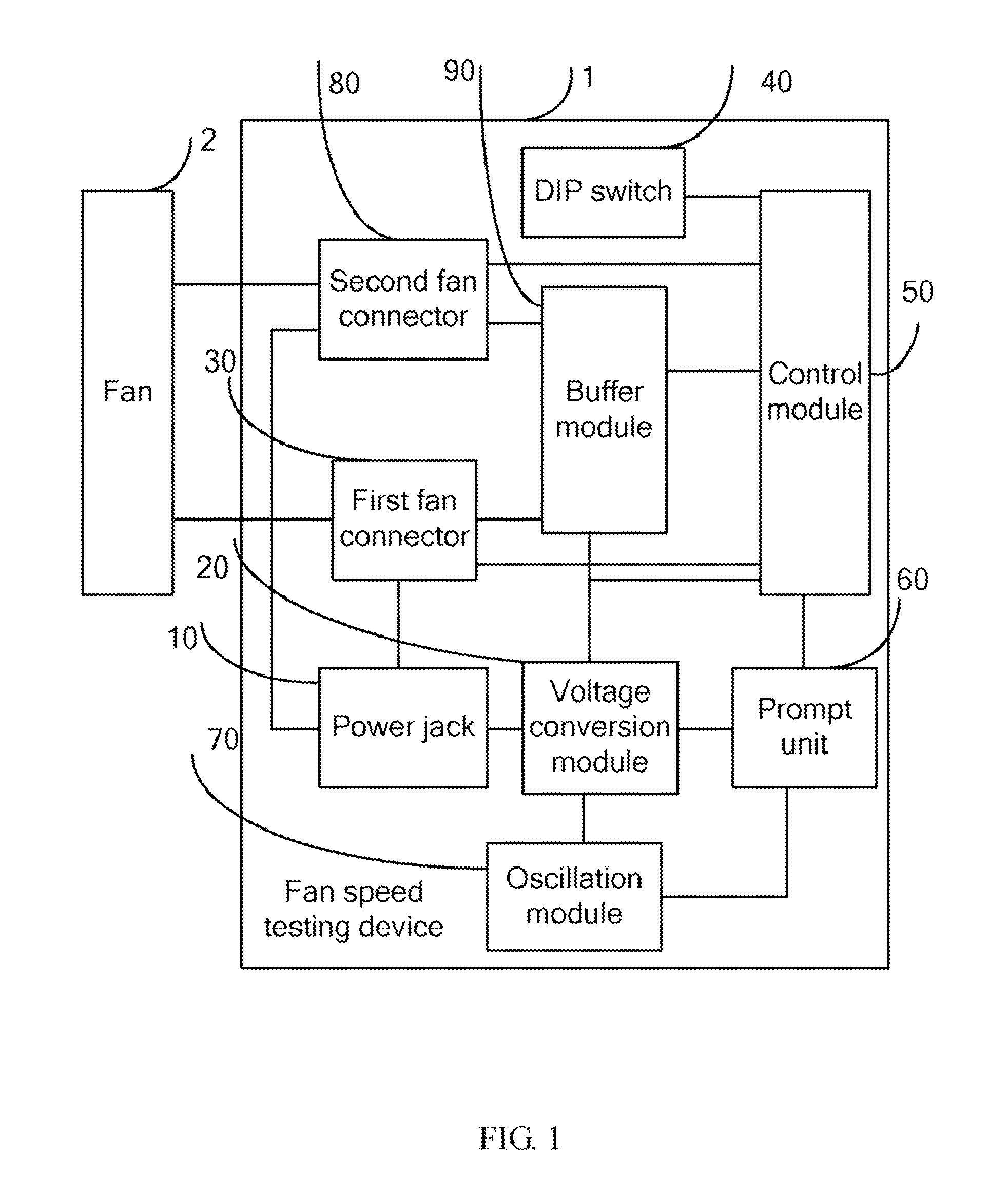
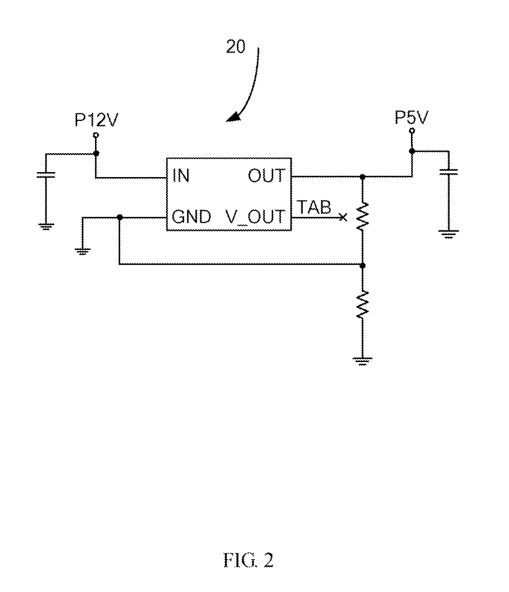
[0015]FIG. 1 shows one embodiment of a fan speed testing device 1. The fan speed testing device 1 includes a power jack 10, a voltage conversion module 20, a first fan connector 30, a dual in-line package switch (DIP switch) 40, and a control module 50. The power jack 10 is configured to receive voltage from a power source (not shown) and supply the received voltage to the first fan connector 30. In the embodiment, the voltage received from the power source is 12V. The voltage conversion module 20 is electrically connected to the power jack 10. The voltage conversion module 20 converts the voltage received by the power jack 10 to a predetermine...


PUM


Abstract

A fan speed testing device is provided. The device includes a power jack, a voltage conversion module, a first fan connector, a DIP switch, and a control module. The first fan connector receives voltage from the power jack and outputs a PWM signal to a fan, receives a first feedback signal from the fan, and outputs the first feedback signal to the control module. The control module receives the predetermined voltage, sets the rotation speed of the fan as marked or predicted by the manufacturer, and outputs the generated PWM signal to the first fan connector. The control module further analyzes the first feedback signal to determine an actual rotation speed of the fan, and outputs the predicted rotation speed of the fan and the first actual rotation speed of the fan, by visual or audible signal to the user for comparison purposes.

Description

BACKGROUND[0001]1. Technical Field[0002]The present disclosure relates to testing devices and, more particularly, to a fan speed testing device.[0003]2. Description of Related Art[0004]During operation of computers, for example, some electronic components, such as CPUs, may generate a lot of heat. Fans in the electronic devices are employed to dissipate heat. Usually, the electronic device employs a number of thermal sensors to detect the temperature of the electronic components. Each sensor is used to detect the temperature of an electronic component. The electronic device generates a PWM signal containing a unique duty cycle corresponding to the detected temperature of one sensor and outputs the PWM signal to the fan cooling the component with the sensor to control the fan to rotate with a certain rotation speed. However, depending on the type, manufacturer, and usage time of the fan, the rotation speed may not reach one certain rotation speed when the same PWM signals are sent to...

Claims


Application Information

Patent Timeline
Patent Type & Authority Applications(United States)
IPC IPC(8): G01P3/489
CPCG01P3/489F04D25/0613F04D27/001
Inventor WU, KANGTIAN, BO
Owner HONG FU JIN PRECISION IND (SHENZHEN) CO LTD
Why Eureka
Try Eureka