
Method of performing shared mesh protection switching

a technology of protection switching and shared mesh, applied in data switching networks, frequency-division multiplexes, instruments, etc., can solve problems such as protocol complexity and erroneous operation of shared mesh protection switching mechanisms, and achieve the effect of fundamentally preventing the abnormal operation of a shared mesh protection switching protocol

Inactive Publication Date: 2014-09-04
ELECTRONICS & TELECOMM RES INST
View PDF8 Cites 7 Cited by
  • Summary
  • Abstract
  • Description
  • Claims
  • Application Information

AI Technical Summary

Benefits of technology

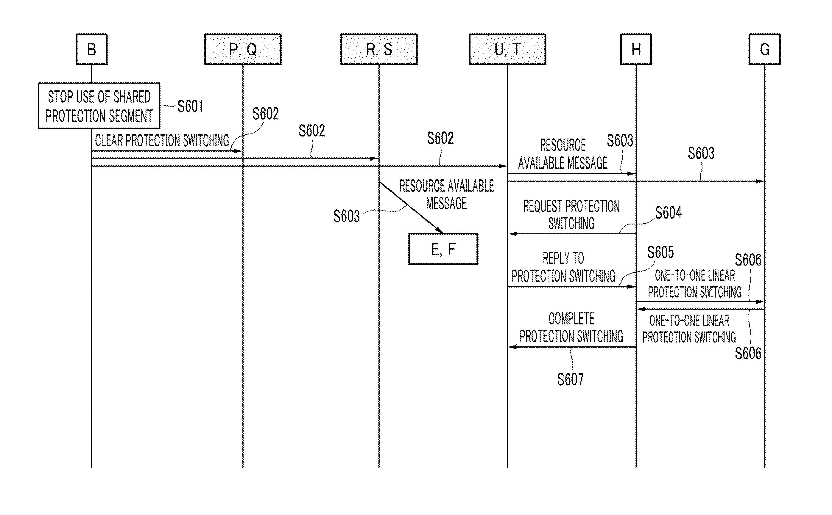
The present invention relates to a method for protective switching in a communication network. The technical effect is to prevent abnormal operation of the shared mesh protection switching protocol and to use conventional 1-phase linear protection switching while addressing congestion during preemption process of stopping the use of shared protection resource by a working path having low priority.

Problems solved by technology

As described above, because an end node having detected a protection switching event reports the protection switching event and simultaneously switches traffic to the protection path, a congestion situation in which traffic exceeding a bandwidth of a shared protection segment is instantaneously injected to a shared protection segment of the protection path may occur.
Further, when congestion occurs at the shared protection segment, a continuity check (CC) message that is sent and received in order to monitor a state of a protection path between endpoints is lost and thus it may be determined that the protection path between endpoints is in a signal failure state.
In this case, because a signal failure of a protection path generally has a higher priority than that of a working path, protection switching to the protection path is cancelled and thus a problem that a shared mesh protection switching mechanism erroneously operates may occur.
However, when using the above 2-phase APS protocol, there is a problem that the conventional linear protection switching mechanism should be modified, the protocol may be complicated, and the protection switching time increases further than that in a linear protection switching method using a conventional 1-phase APS protocol.

Method used


Image

  • Method of performing shared mesh protection switching
  • Method of performing shared mesh protection switching
  • Method of performing shared mesh protection switching

Examples


Embodiment Construction

[0039]In the following detailed description, only certain exemplary embodiments of the present invention have been shown and described, simply by way of illustration. As those skilled in the art would realize, the described embodiments may be modified in various different ways, all without departing from the spirit or scope of the present invention. Accordingly, the drawings and description are to be regarded as illustrative in nature and not restrictive. Like reference numerals designate like elements throughout the specification.

[0040]Throughout this specification and the claims that follow, unless explicitly described to the contrary, the word “comprise” and variations such as “comprises” or “comprising” will be understood to imply the inclusion of stated elements but not the exclusion of any other elements.

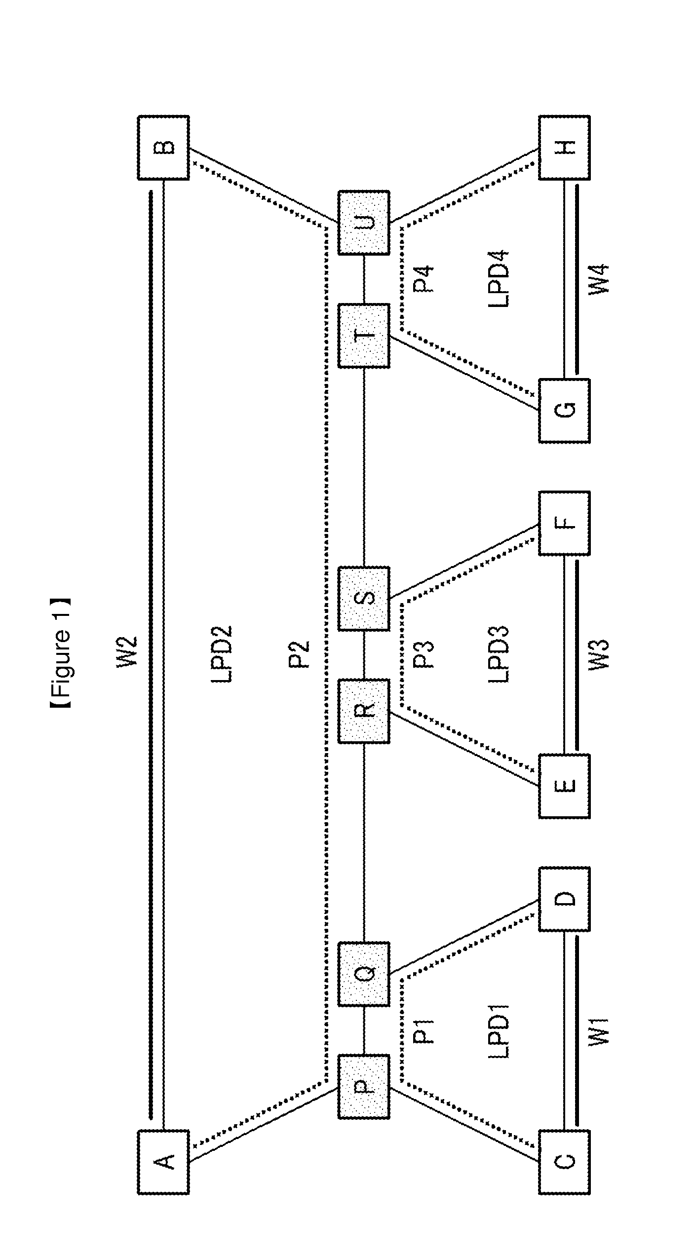
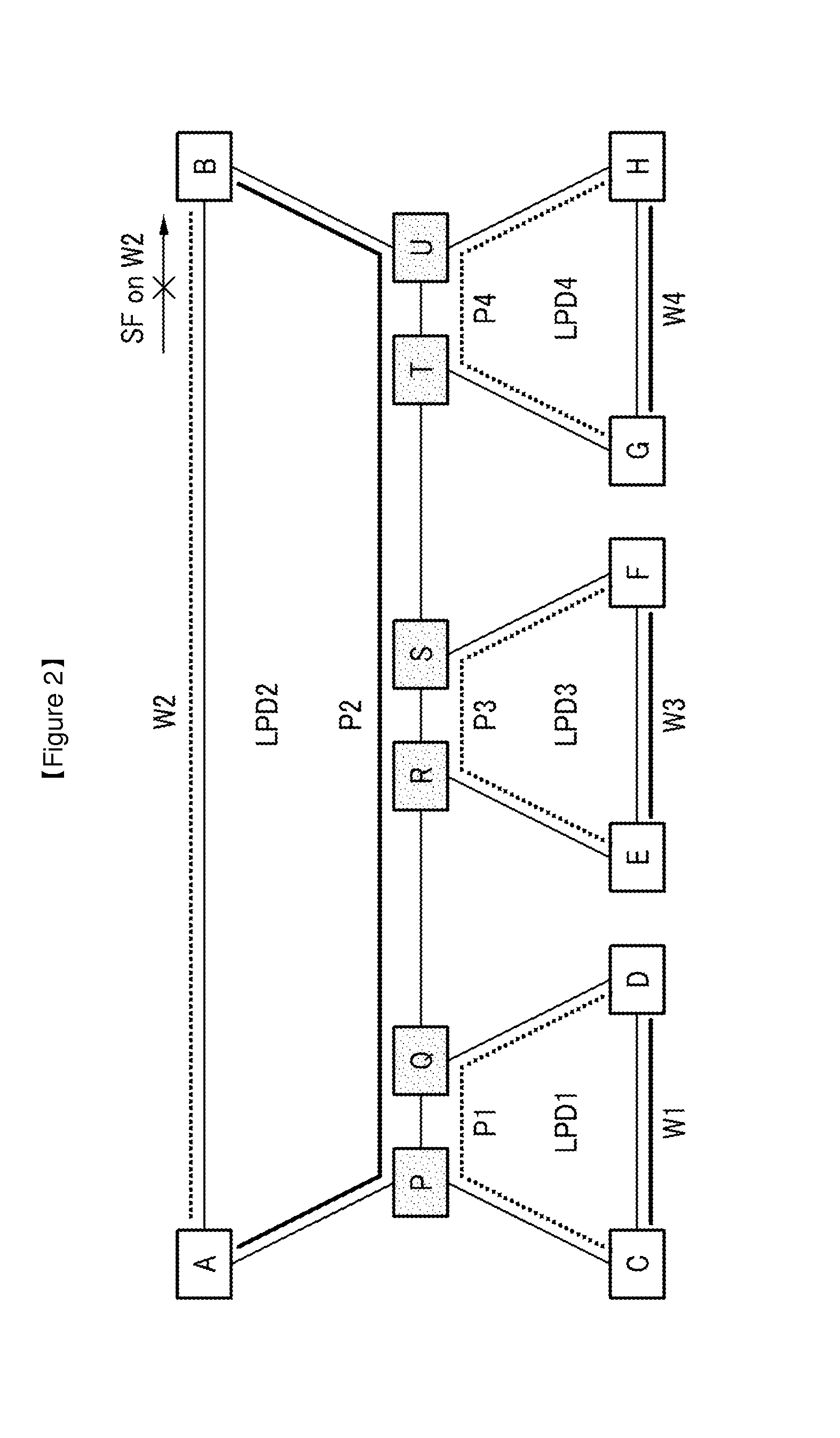
[0041]FIG. 1 is a diagram illustrating a sharing mesh protection domain according to an exemplary embodiment of the present invention.

[0042]Referring to FIG. 1, a sharing mesh...


PUM


Abstract

A method of performing shared mesh protection switching in which congestion does not occur in a sharing segment and that quickly performs linear protection switching while using a 1-phase automatic protection switching protocol is provided. For protection switching of a working path that is included in a end-to-end linear protection domain having a high priority, because of congestion that may occur in a pre-emption process of stopping use of a shared protection segment of a working path that is included in a end-to-end linear protection domain having a low priority, a signal failure occurs at a protection path, and thus operation of a shared mesh protection switching protocol abnormally can be prevented.

Description

TECHNICAL FIELD[0001]The present invention relates to a method of performing shared mesh protection switching that shares a protection path.BACKGROUND ART[0002]Protection switching is a method of resuming traffic transmission when traffic transmission is stopped, when a signal failure occurs in a network. A protection switching method is classified into linear protection switching, ring protection switching, and mesh protection switching according to topology of a network.[0003]Linear protection switching operates within a linear protection domain. That is, in a linear protection switching method, both endpoints that send and receive traffic and a working path and a protection path that connect the endpoints are defined as a linear protection domain, and by transmitting / receiving a message between endpoints according to a protocol, a protection switching function operates.[0004]Mesh protection switching sets a linear protection domain for a point-to-point connection one by one and e...

Claims


Application Information

Patent Timeline
Patent Type & Authority Applications(United States)
IPC IPC(8): H04L12/24
CPCH04L41/0668H04L41/0663H04L45/22H04L45/28
Inventor CHEUNG, TAESIKRYOO, JEONG-DONG
Owner ELECTRONICS & TELECOMM RES INST
Learn More