Terminal device, base station device, transmission method and reception method

Active Publication Date: 2014-09-04
PANASONIC INTELLECTUAL PROPERTY CORP OF AMERICA
View PDF8 Cites 33 Cited by
  • Summary
  • Abstract
  • Description
  • Claims
  • Application Information

AI Technical Summary

Benefits of technology

[0037]According to the present invention, it is possible to effectively utilize a downlink communication subframe while enabling a dynamic switching to a frame for

Problems solved by technology

However, since the UL-DL configuration is a configuration common to all the terminals within a cell, switching is generall

Method used


Image

  • Terminal device, base station device, transmission method and reception method
  • Terminal device, base station device, transmission method and reception method
  • Terminal device, base station device, transmission method and reception method

Examples


embodiment

Overview of Communication System

[0052]A communication system according to an embodiment of the present invention includes base station 100 and terminal 200. Base station 100 is an LTE-A base station and terminal 200 is an LTE-A terminal.

[Configuration of Base Station 100]

[0053]FIG. 6 is a block diagram illustrating a configuration of base station 100 according to Embodiment 1 of the present invention. In FIG. 6, base station 100 includes configuration section 101, control section 102, search space configuration section 103, PDCCH generating section 104, coding / modulating sections 105, 106 and 107, assignment section 108, multiplexing section 109, inverse fast Fourier transform (IFFT) section 110, cyclic prefix (CP) adding section 111, RF transmitting section 112, antenna 113, RF receiving section 114, CP removing section 115, fast Fourier transform (FFT) section 116, extracting section 117, inverse discrete Fourier transform (IDFT) section 118, data receiving section 119, and ACK / NA...


PUM


Abstract

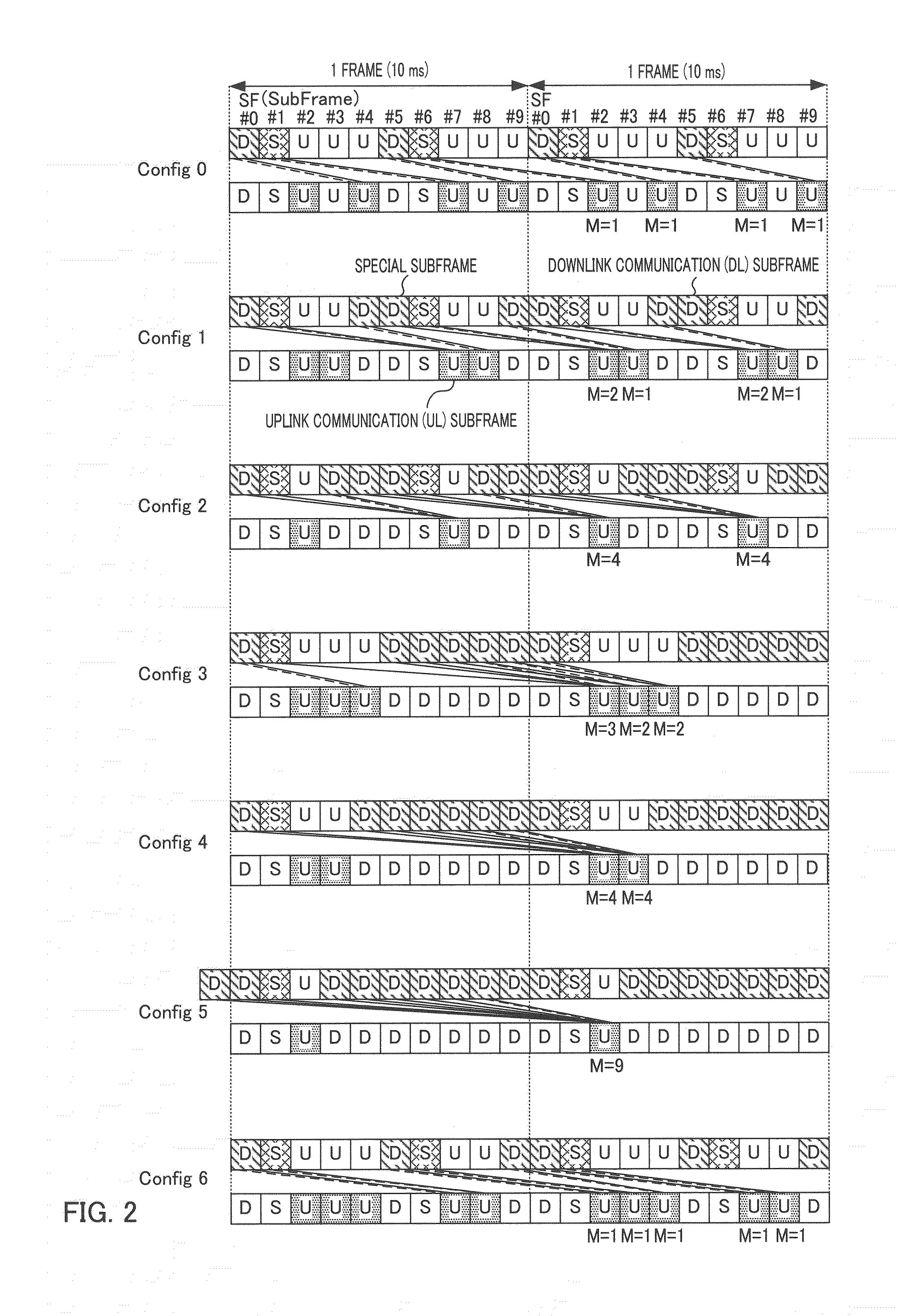
The present disclosure enables dynamic switching to a frame format different from the UL-DL configuration set by an SIB, and in particular switching to a downlink communication subframe from an uplink communication subframe, while also enabling effective utilization of downlink communication subframes. A base station uses “UL/DL communication subframe switching information” included in a DCI sent by a downlink communication subframe to instruct a terminal whether or not to perform uplink communication to a DCI using one or more uplink-specific communication subframes, and also gives instructions whether to perform uplink communication or downlink communication on an uplink communication subframe switchable to a downlink communication subframe.

Description

TECHNICAL FIELD[0001]The present invention relates to a terminal apparatus, a base station apparatus, a transmission method and a reception method that switch between frame formats.BACKGROUND ART[0002]In 3rd Generation Partnership Project Radio Access Network Long Term Evolution (3GPP-LTE (hereinafter referred to as LTE)), Orthogonal Frequency Division Multiple Access (OFDMA) is adopted as a downlink communication scheme, and Single Carrier Frequency Division Multiple Access (SC-FDMA) is adopted as an uplink communication scheme (e.g., see NPL-1, NPL-2, and NPL-3).[0003]In LTE, a radio communication base station apparatus (hereinafter abbreviated as “base station”) performs communication by allocating a resource block (RB) in a system band to a radio communication terminal apparatus (hereinafter abbreviated as “terminal”) for every time unit called “subframe.” The base station also transmits assignment control information (i.e., L1 / L2 control information) for indicating the result o...

Claims


Application Information

Patent Timeline
IPC IPC(8): H04L5/00
CPCH04L5/0037H04L5/001H04L5/0053H04L5/0096H04L5/14
Inventor OIZUMI, TORUIMAMURA, DAICHI
Owner PANASONIC INTELLECTUAL PROPERTY CORP OF AMERICA
Why Eureka
Try Eureka