Exposure system and hole array

Inactive Publication Date: 2005-01-06
FUJIFILM CORP +1
View PDF15 Cites 15 Cited by
  • Summary
  • Abstract
  • Description
  • Claims
  • Application Information

AI Technical Summary

Benefits of technology

[0019] In view of the foregoing observations and description, the primary object of the present invention is to provide an exposure system in which the efficienc

Problems solved by technology

Further, in such a reading light exposure system, there has been a problem that the line beam on the electrostatic recording medium is not uniform in its intensity in the LED arranging direction.
Such nonuniformity in intensity can deteriorate reliability of the image information read out.
However, the reading light exposure system shown in FIGS. 7A and 7B gives rise to a problem that the efficiency of utilization of the reading light beam emitted from the line source is low since a pinhole array in which a number of circular or square pinholes are arranged is used.
When the pinholes are increased in size, though the efficiency of utilization of the reading light beam emitted from the line source

Method used


Image

  • Exposure system and hole array
  • Exposure system and hole array
  • Exposure system and hole array

Examples


first embodiment

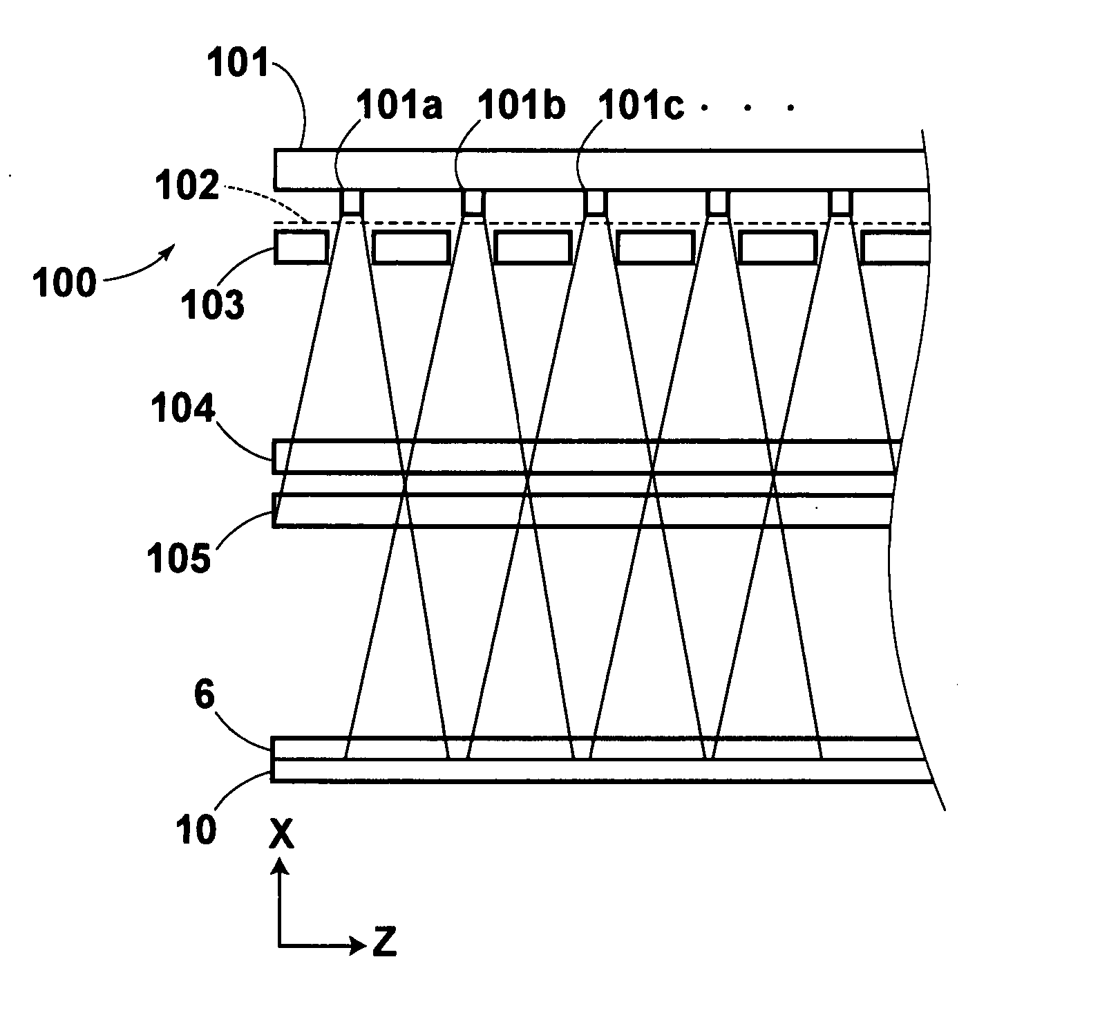
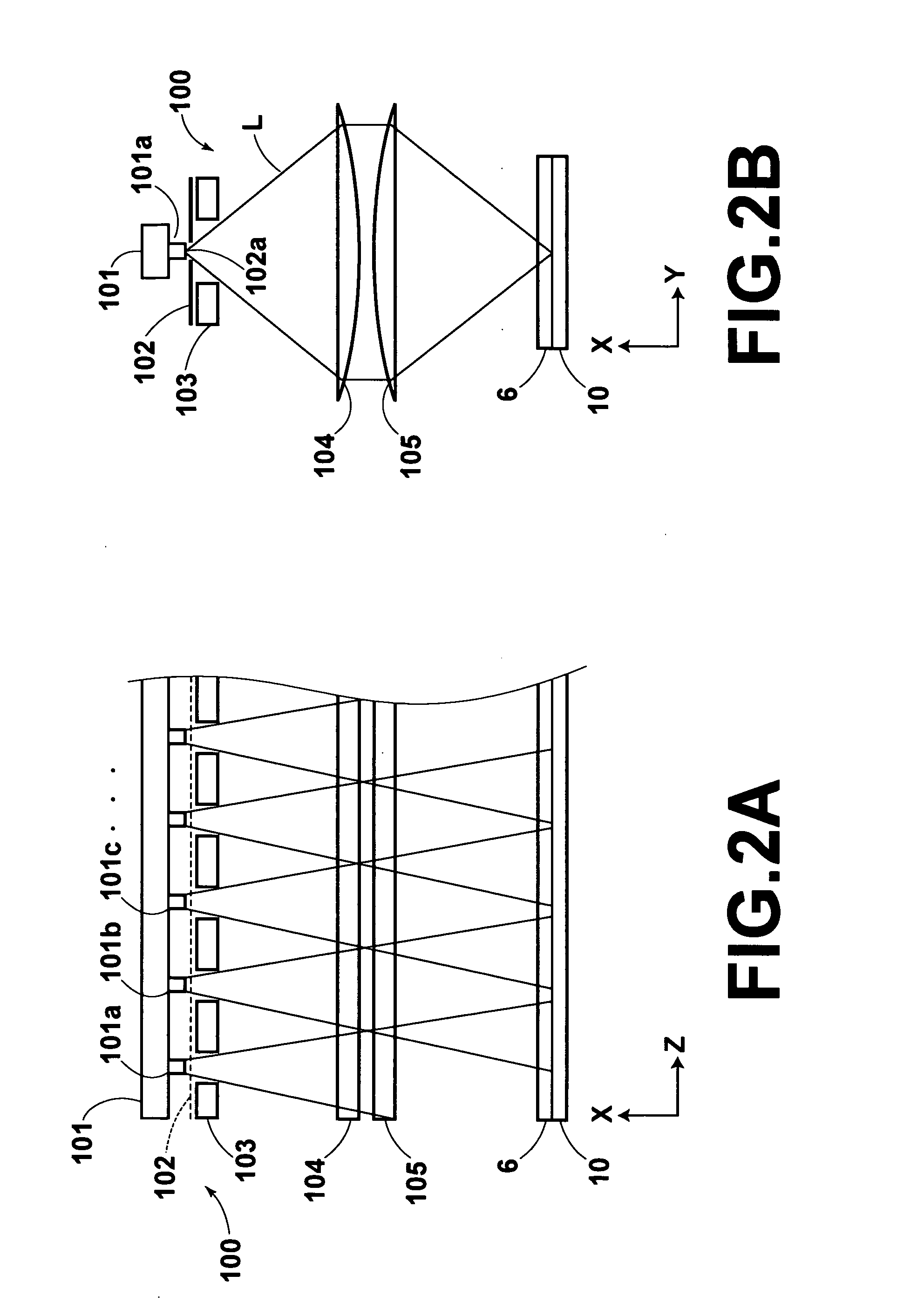
[0087] The reading light exposure system 100 in accordance with the present invention employed in the radiation image read-out system will be described with reference to FIG. 2A and 2B, hereinbelow. FIG. 2A is a side view of the reading light exposure system 100 as viewed in the Y-direction (a direction perpendicular to the LED arranging direction), and FIG. 2B is a cross-sectional view of the same taken along a plane parallel to the X-Y plane. The X-direction is a direction of travel of the reading light beam L and the Z-direction is the LED arranging direction (the direction in which the LED chips are arranged).

[0088] As shown in FIGS. 2A and 2B, the reading light exposure system 100 of this embodiment comprises a line source 101 formed by a plurality of LED chips 101a, 101b, 101c . . . linearly arranged in the Z-direction, a slit 102 having an opening extending in the Z-direction (e.g., at intervals of 1 mm), a pinhole array 103 having pinholes formed at the same intervals as the...

second embodiment

[0102] A pinhole array 310 in accordance with the present invention will be described with reference to FIGS. 10 to 12, hereinbelow. The pinhole array 310 of this embodiment is 1.5 mm, 200 mm and 1 mm respectively in Y-, Z- and X-directions. Pinholes 310a, 310b, 310c . . . are 500 μm squares and are formed at intervals of 1 mm, the same intervals as the pitches at which the LED chips 101a, 101b, 101c . . . are arranged. As shown in FIG. 11, the pinhole array 310 limits the angles of divergence of the light beams emitted from the LED chips 101a, 101b, 101c . . .

[0103] The pinhole array 310 is formed by superposing and bonding as shown in FIG. 11 one on another four array plates 311 each of which is about 250 μn in thickness and is provided with openings 311a, 311b, 311c . . . which are 500 μm squares and are formed at intervals of 1 mm, the same intervals as the pitches at which the LED chips 101a, 101b, 101c . . . are arranged as shown in FIG. 12. Each of the array plates 311 is a p...


PUM


Abstract

A reading light exposure system scans an image recording medium with a reading light beam. The reading light exposure system includes a line source emitting the reading light beam, an optical means which converges the reading light beam emitted from the line source in a direction perpendicular to the longitudinal direction of the line source, and a pinhole array having a number of pinholes which limit the angle of divergence of the reading light beam in the longitudinal direction of the line source with respect to the optical axis of the optical means. The length of each of the pinholes in the direction perpendicular to the longitudinal direction of the line source is larger than the length thereof in the longitudinal direction of the line source.

Description

BACKGROUND OF THE INVENTION [0001] 1. Field of the Invention [0002] This invention relates to an exposure system for exposing an image recording medium to a recording light by scanning the image recording medium with the recording light to read the image recorded on the recording medium, and more particularly to such an exposure system having a hole array. [0003] 2. Description of the Related Art [0004] There has been known an image reading system in which a photoconductive body such as a selenium plate sensitive to X-rays is employed as an electrostatic recording medium, the electrostatic recording medium is exposed to radiation such as X-rays carrying thereon radiation image information to store a latent image electric charge representing the radiation image, and then the radiation image information is read out by scanning the electrostatic recording medium with a laser beam and detecting the electric current generated in the electrostatic recording medium upon exposure to the las...

Claims


Application Information

Patent Timeline
IPC IPC(8): H04N1/028
CPCH04N1/02815H04N1/02885H04N1/02865
Inventor HAKAMATA, KAZUO
Owner FUJIFILM CORP
Why Eureka
Try Eureka