Voltage regulator

a voltage regulator and voltage regulator technology, applied in the direction of electric variable regulation, process and machine control, instruments, etc., can solve the problems of increasing the output voltage, taking time to control, and excessive curren

Active Publication Date: 2014-09-11
ABLIC INC
View PDF10 Cites 10 Cited by
  • Summary
  • Abstract
  • Description
  • Claims
  • Application Information

AI Technical Summary

Benefits of technology

[0011]According to the voltage regulator according to one embodiment of the present invention, the output voltage can be controlled to a predetermined voltage quickly after an undershoot occurs in the output voltage.

Problems solved by technology

In the related-art voltage regulator, however, there is a problem in that it may take time to control so that a predetermined output voltage Vout may be output from the state in which an undershoot occurs and the PMOS transistor 120 is turned fully on.
Further, there is another problem in that an output current may become excessive to increase the output voltage Vout while the output voltage Vout is controlled to be a predetermined output voltage from the state in which an undershoot occurs and the PMOS transistor is turned fully on.

Method used


Image

  • Voltage regulator
  • Voltage regulator
  • Voltage regulator

Examples


embodiment

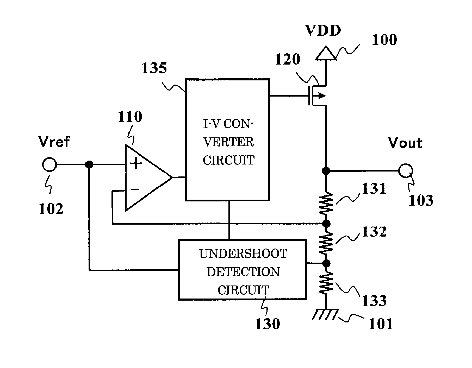
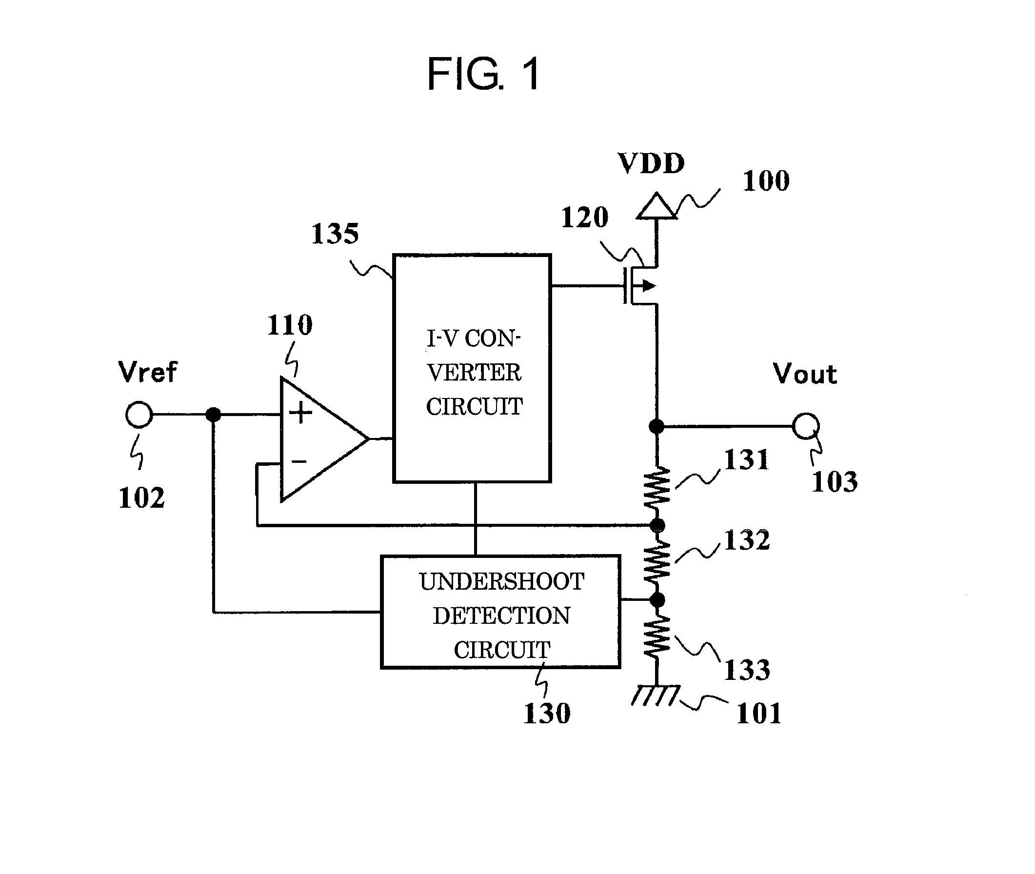
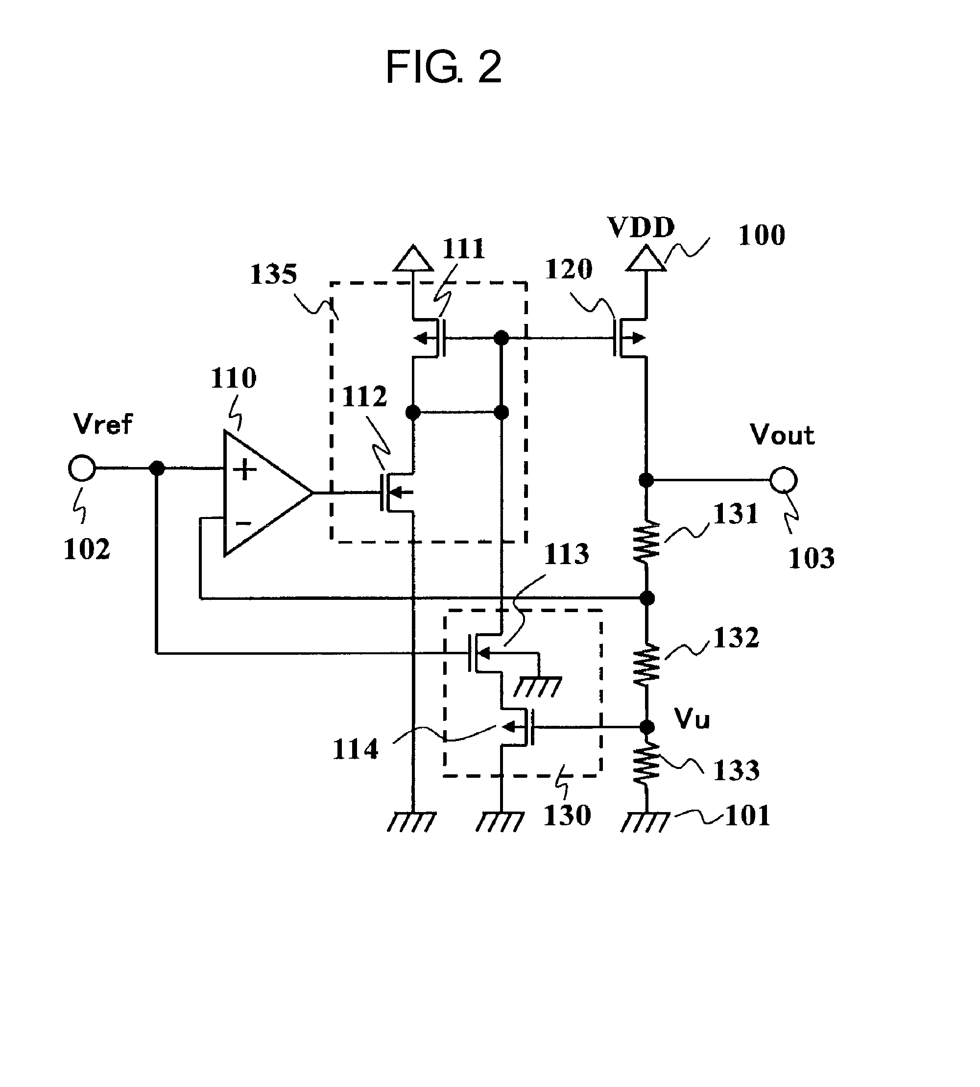
[0017]FIG. 1 is a block diagram of a voltage regulator according to an embodiment of the present invention. The voltage regulator according to this embodiment includes an error amplifier 110, a PMOS transistor 120, resistors 131, 132, and 133, an undershoot detection circuit 130, an I-V converter circuit 135, a power supply terminal 100, a ground terminal 101, a reference voltage terminal 102, and an output terminal 103. The PMOS transistor 120 operates as an output transistor. FIG. 2 is a circuit diagram of the voltage regulator according to this embodiment. The undershoot detection circuit 130 includes NMOS transistors 113 and 114. The I-V converter circuit 135 includes a PMOS transistor 111 and an NMOS transistor 112.

[0018]Next, connections in the voltage regulator according to this embodiment are described. The error amplifier 110 has a non-inverting input terminal connected to the reference voltage terminal 102, an inverting input terminal connected to a connection point betwee...


PUM


Abstract

Provided is a voltage regulator capable of controlling an output voltage to a predetermined voltage quickly after an undershoot occurs in the output voltage. The voltage regulator includes: an undershoot detection circuit configured to detect a voltage that is based on an output voltage of the voltage regulator, and output a current corresponding to an undershoot amount of the output voltage; and an I-V converter circuit configured to control a current flowing through an output transistor based on a current controlled by an output of an error amplifier and a current flowing from the undershoot detection circuit.

Description

RELATED APPLICATIONS[0001]This application claims priority under 35 U.S.C. §119 to Japanese Patent Application Nos. 2013-044166 filed on Mar. 6, 2013 and 2014-002973 filed on Jan. 10, 2014, the entire contents of which are hereby incorporated by reference.BACKGROUND OF THE INVENTION[0002]1. Field of the Invention[0003]The present invention relates to an improvement in undershoot in a voltage regulator.[0004]2. Description of the Related Art[0005]FIG. 3 illustrates a circuit diagram of a related-art voltage regulator. The related-art voltage regulator includes an error amplifier 110, PMOS transistors 120, 201, and 204, NMOS transistors 202, 203, and 205, resistors 231, 232, 233, and 234, a comparator 210, an inverter 211, an offset voltage generation circuit 212, a power supply terminal 100, a ground terminal 101, a reference voltage terminal 102, and an output terminal 103.[0006]The error amplifier 110 controls a gate of the PMOS transistor 120, and an output voltage Vout is thereby...

Claims


Application Information

Patent Timeline
Patent Type & Authority Applications(United States)
IPC IPC(8): G05F1/46
CPCG05F1/46G05F1/565
Inventor UTSUNOMIYA, FUMIYASU
Owner ABLIC INC
Why Eureka
Try Eureka