Projector and Electronic Apparatus Having Projector Function

a technology of electronic equipment and projector, which is applied in the field of projectors and electronic equipment having a projector function, can solve the problems of not being able to properly introduce the laser, taking time and labor to adjust the optical system in order, and disadvantageously taking time and labor to achieve the effect of reducing the distance (detection height), reducing the detection accuracy of the detection object, and increasing the distan

Inactive Publication Date: 2014-09-11
FUNAI ELECTRIC CO LTD
View PDF4 Cites 8 Cited by
  • Summary
  • Abstract
  • Description
  • Claims
  • Application Information

AI Technical Summary

Benefits of technology

[0029]In the aforementioned electronic apparatus having a projector function according to the second aspect, the control portion is preferably configured to control the position adjustment portion to adjust the relative positions of the beam receiving portion and the lens, in order to adjust the distance from the projection plane for detecting the operation performed with the detection object in response to an application corresponding to the projected image. According to this structure, the control portion can reduce the distance (detection height) from the projection plane for detecting the operation performed with the detection object when the interval between operati

Problems solved by technology

However, the projector module described in the aforementioned Japanese Patent Laying-Open No. 2009-258569 may not be capable of properly introducing the laser beam reflected by the measurement object into the photodiode, due to arrangement accuracy (assemblin

Method used


Image

  • Projector and Electronic Apparatus Having Projector Function
  • Projector and Electronic Apparatus Having Projector Function
  • Projector and Electronic Apparatus Having Projector Function

Examples


Embodiment Construction

[0038]An embodiment of the present invention is now described with reference to the drawings.

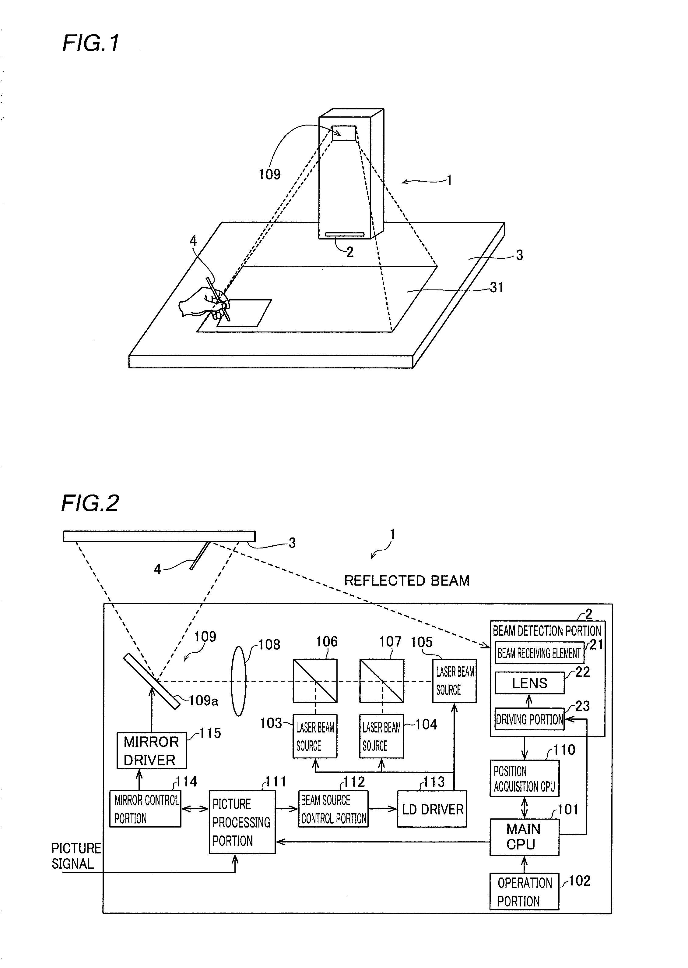
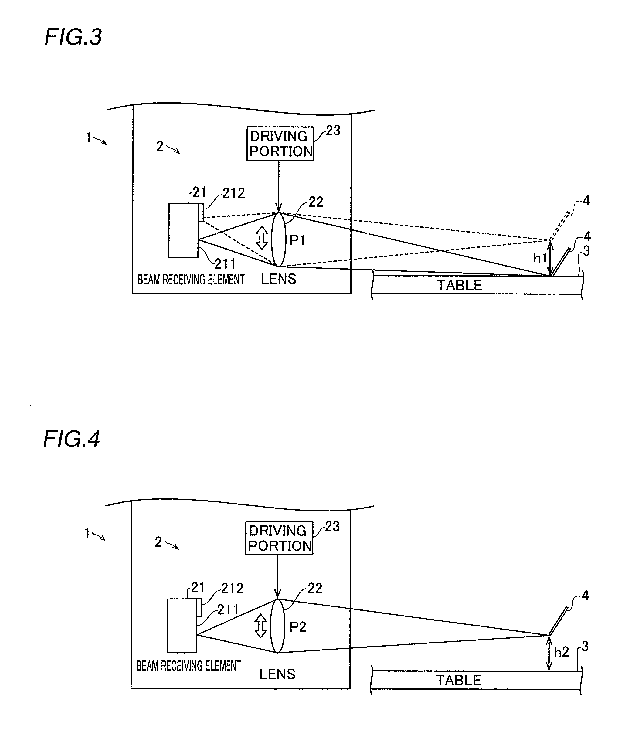
[0039]First, the structure of a projector 1 according to the embodiment of the present invention is described with reference to FIGS. 1 to 4.

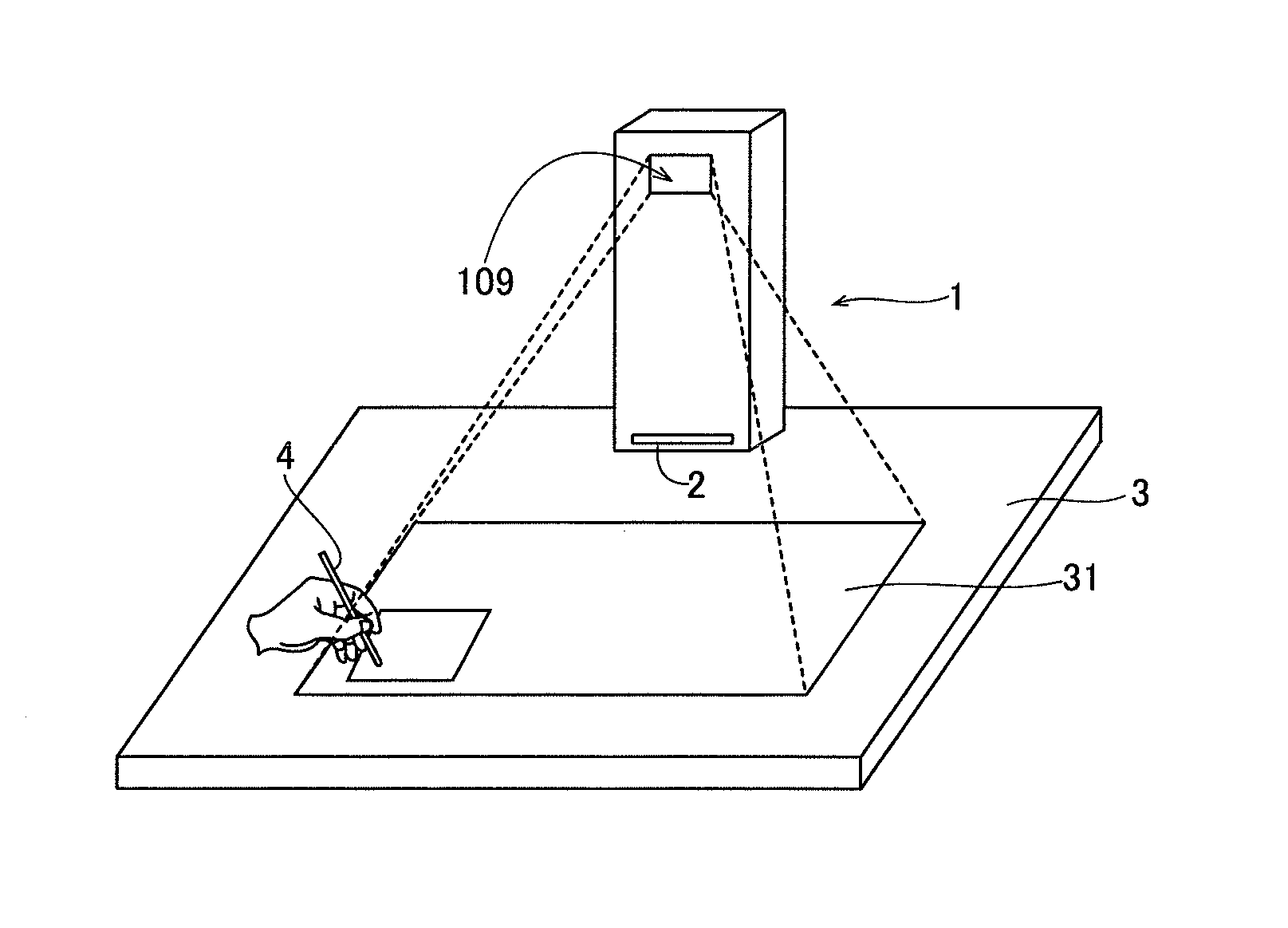
[0040]The projector 1 according to the embodiment of the present invention is configured to be used in a state arranged on a table 3, as shown in FIG. 1. This projector 1 is configured to project an image 31 on the upper surface of a projection area such as the table 3. Further, the projector 1 is configured to accept an operation such as a touch operation performed on the image 31 with an operating element such as a touch pen 4. The table 3 is an example of the “projection area” in the present invention, and the touch pen 4 is an example of the “detection object” in the present invention. The projector 1 may be an electronic apparatus such as a portable information terminal. The projector 1 is an example of the “electronic apparatus having a projector ...


PUM


Abstract

This projector includes a laser beam generation portion, an image projection portion including a scanning portion and projecting an image on a projection area, a beam receiving portion receiving a laser beam reflected by a detection object through a lens, a control portion, and a position adjustment portion adjusting relative positions of the beam receiving portion and the lens in a direction orthogonal to the optical axis direction of the laser beam received by the beam receiving portion.

Description

BACKGROUND OF THE INVENTION[0001]1. Field of the Invention[0002]The present invention relates to a projector and an electronic apparatus having a projector function, and more particularly, it relates to a projector and an electronic apparatus having a projector function each including a laser beam generation portion.[0003]2. Description of the Background Art[0004]A projector including a laser beam generation portion is known in general, as disclosed in Japanese Patent Laying-Open No. 2009-258569, for example.[0005]The aforementioned Japanese Patent Laying-Open No. 2009-258569 discloses a projector module (projector) including a laser diode outputting a laser beam, a projector scanning means scanning the laser beam and projecting an image on a projection area, a photodiode receiving the laser beam reflected by a measurement object and a control means detecting that the measurement object has touched the projected image when the photodiode receives the laser beam. This projector modul...

Claims


Application Information

Patent Timeline
IPC IPC(8): G03B21/14
CPCG03B21/142G06F3/0423H04N9/3129H04N9/3194
Inventor KUKI, KOHEI
Owner FUNAI ELECTRIC CO LTD
Why Eureka
Try Eureka