Multi-leaf collimators

a collimator and multi-leaf technology, applied in the direction of bearings, linear bearings, mechanical instruments, etc., can solve the problems of damage to the healthy tissue around the tumour, damage to the tissue making up the tumour, and potential damage, so as to drive the leaves more quickly, deliver more quickly, rotate more quickly

Active Publication Date: 2014-09-11
ELEKTA AB
View PDF8 Cites 3 Cited by
  • Summary
  • Abstract
  • Description
  • Claims
  • Application Information

AI Technical Summary

Benefits of technology

[0006]The present invention seeks to improve on existing designs of multi-leaf collimator “MLC”). Specifically, the invention aims to provide an MLC that is able to drive the leaves more quickly. At present, the MLC leaf speed is one of the limiting factors on the overall speed of the radiotherapy apparatus; increasing this could allow some treatments to be delivered more quickly, and could allow the gantry to rotate more quickly thereby assisting with combined radiotherapy / Computed Tomography arrangements.
[0008]The rolling elements can be retained within a recirculating path, allowing them to move smoothly and support the leaf regardless of the extent of its movement. Ideally, the rolling elements support the edge of the leaf over a limited part of the recirculating path, with the remainder acting as a return path.
[0009]The rolling elements can be driven by a drive motor, thereby to drive the leaf and / or reduce the frictional resistance met by the rolling elements in the recirculating path. The drive motor preferably contacts the rolling elements at a part of the recirculating path located outside the limited part, thus spacing the driver motor from the leaf and assisting with the packaging of the necessary elements in what is often a limited volume. The leaf can then comprise formations extending from an edge supported by the bearing and shaped to engage with the rolling elements and be driven thereby; those formations can be formed integrally with the remainder of the leaf or be made up of parts engaging with the leaf.
[0010]The rolling surfaces of the rolling elements can also have a rolling contact with an edge of the leaf, thereby to define a true rolling-element bearing with the leaf being supported by a rolling motion only and without any need for sliding. The rolling elements may form part of a linear bearing, which is aligned with the elongate leaves so that the rolling elements are free to roll in the same direction as the leaf moves. This will considerably reduce the frictional resistance to movement of the leaf and allow the leaves to be safely moved much more quickly. At present, one limitation on the speed of leaf movement is the force which can be exerted on the leaf without buckling the drive screws; reducing the force necessary to overcome friction will therefore allow faster movement.

Problems solved by technology

These beams pass through the patient's anatomy and cause harm to the tissue making up the tumour.
The beam is however also apt to cause damage to healthy tissue around the tumour, albeit at a lower rate, and thus efforts are made to limit this potential for damage.

Method used


Image

  • Multi-leaf collimators
  • Multi-leaf collimators
  • Multi-leaf collimators

Examples


Embodiment Construction

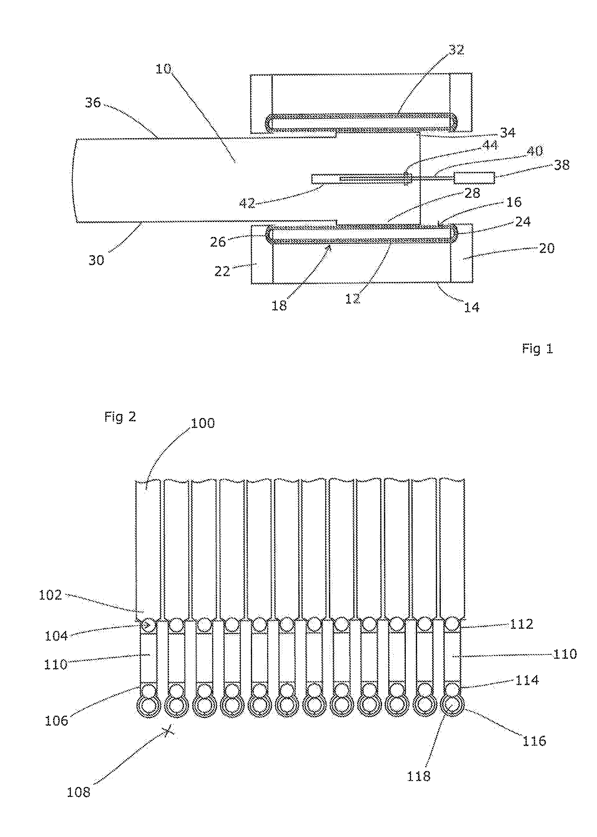
[0018]FIG. 1 shows a side view of a single leaf 10 supported by a single ball 12 race set up as an undriven rolling-element bearing. Of course, a practical multi-leaf collimator will include many leaves (as its name suggests), arranged side-by-side and moveable independently back and forth (i.e. from left to right and vice-versa in FIG. 1). These can then act in concert to shape the beam in the manner described above. For clarity, the other leaves are omitted from FIG. 1.

[0019]The ball race is defined in a support structure 14 that includes an exposed open channel 16 allowing the leaf to rest on the ball race 12, and a return channel 18. End caps 20, 22 include U-shaped channels 24, 26 to connect the open channel 16 and the return channel 18 and thus define a complete recirculating path for the ball race 12. The leaf 12 includes a support section 28 that extends below the lower edge 30 of the remainder of the leaf 10, into the open channel 16 to rest on the exposed part of the ball ...


PUM


Abstract

The leaves of a multi-leaf collimator can be driven more easily and hence more quickly if they are supported on a ball-race instead of in a sliding groove. A recirculating path is preferred, in which the rolling elements of the ball-race support the leaf over part of their path and then return to a start of the path. In addition, the rolling elements could be driven by a drive screw in order to drive the leaf.

Description

FIELD OF THE INVENTION[0001]The present invention relates to multi-leaf collimators. These are commonly used in radiotherapy apparatus in order to provide a variable and tailorable collimation to the x-ray beam.BACKGROUND ART[0002]Radiotherapy is a technique by which high-energy x-ray beams are directed towards a tumour or other lesion within a patient. These beams pass through the patient's anatomy and cause harm to the tissue making up the tumour. The beam is however also apt to cause damage to healthy tissue around the tumour, albeit at a lower rate, and thus efforts are made to limit this potential for damage.[0003]One way of doing so is to direct the beam toward the tumour from a range of different directions. The result is that whereas the tumour (or some part of it) is in the beam continuously, the surrounding healthy tissue is only exposed for a shorter period, thus reducing the dose applied to that specific region. Typically, radiotherapy sources are therefore mounted on a ...

Claims


Application Information

Patent Timeline
Patent Type & Authority Applications(United States)
IPC IPC(8): G21K1/04
CPCG21K1/046F16C29/008F16C29/06Y10T74/19181
Inventor PERKINS, CLIFFORD WILLIAM
Owner ELEKTA AB
Why Eureka
Try Eureka