Pump system

a technology of pump system and pump head, which is applied in the direction of water supply mains, water supply installation, fluid pressure control, etc., can solve the problem of difficulty in maintaining the desired minimum pressure in all parts of the water supply main, i.e., in all branches, and achieve the effect of greater accuracy of recognition

Active Publication Date: 2014-09-11
GRUNDFOS HLDG
View PDF5 Cites 18 Cited by
  • Summary
  • Abstract
  • Description
  • Claims
  • Application Information

AI Technical Summary

Benefits of technology

[0036]According to a further preferred development of the method, it is likewise possible to localize a probable location of a leakage in the water supply mains at least to one of the part regions. This is preferably effected by way of the comparison of a pressure loss actually measured for a part region, with the pressure loss to be expected according to the associated model for this part region. Thereby, preferably a leakage is then ascertained in a part region, if in this, the actual pressure loss is equal or greater than the expected pressure loss. This is particularly the case if the actual pressure loss in all other part regions corresponds to the expected pressure loss or however is smaller than the expected pressure loss. Inasmuch as this is concerned, the division of the complete mains into different part regions with individual models for the pressure loss of these part regions has the advantage that these models, apart from the regulation or control of the pump unit, can be simultaneou

Problems solved by technology

Inasmuch as this is concerned, it is difficult to always maintain a desired m

Method used


Image

  • Pump system
  • Pump system
  • Pump system

Examples


Embodiment Construction

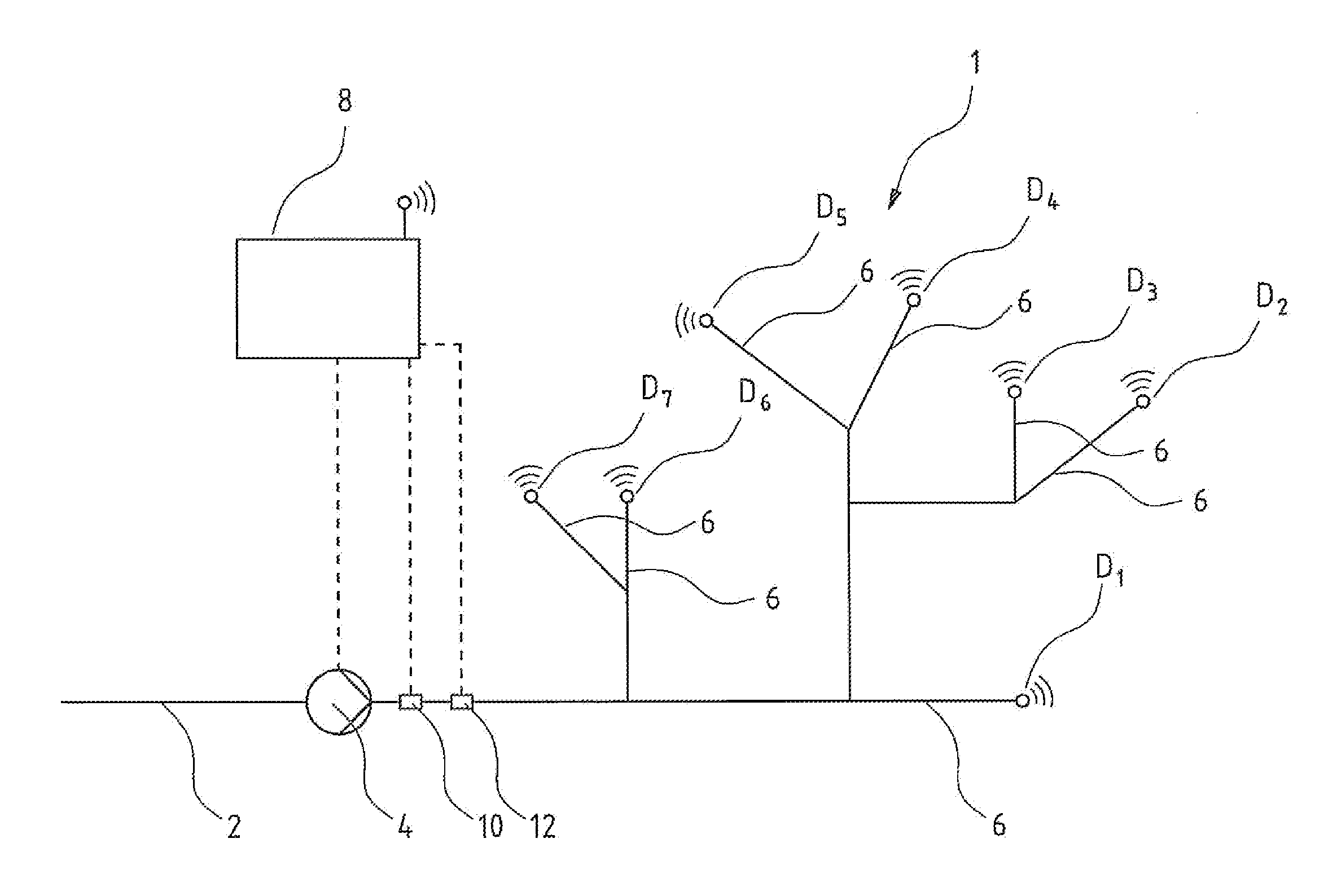
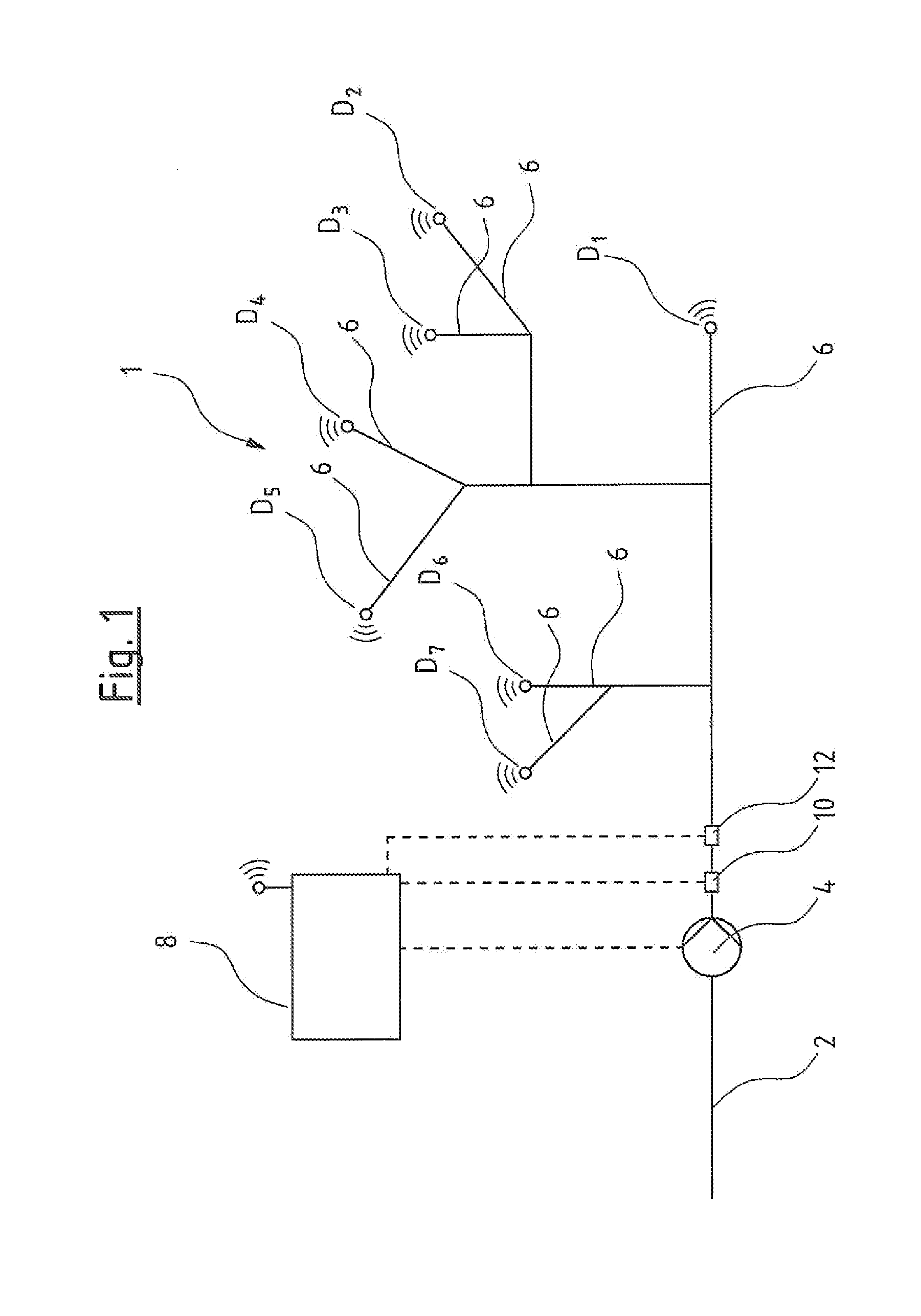
[0045]FIG. 1 schematically shows a water supply mains having a pump system according to an embodiment of the invention. The water supply mains comprises a feed conduit 2, in which a pump unit 4, for example one or more pump assemblies, is arranged. The water supply mains branches into several branches 6 downstream of the pump unit 4. Pressure sensor units D(D1 . . . Dn) are arranged in the shown individual branches 6 at critical points. In the example shown here, the pressure sensor units D are equipped with radio communication modules, which permit a data transmission, via a mobile network according to the SMS standard, to a control device 8. The pressure sensor units D moreover comprise measured value memories, in which pressure measured values with a time stamp and stored at different points in time are stored, so that the individual pressure measured values can be assigned to exact points in time at which they were acquired. The pressure sensor units D are designed such that the...


PUM


Abstract

A pump system for a water supply mains has at least one pump device, a pressure detecting sensor at the pressure side of the pump device, a flow detecting sensor of the pump device, several pressure sensor units (D) remote arranged remotely from the pump device in different part regions of the mains, and a pump control device. The control device includes a model formation module designed in each case to produce a model (A) representing pressure loss from the pressure sensor to the position of the respective pressure sensor unit (D), based on several pressure measured values of at least two pressure sensor units (D) for the at least two associated part regions. The control device is designed for regulation of the pump device based on produced models (A), as well as to a corresponding method for regulation of a pump device in a water supply mains.

Description

BACKGROUND OF THE INVENTION[0001]The invention relates to a pump system for a water supply mains, as well as to a method for the regulation (closed-loop control) of a pump device in a water supply mains.[0002]Water supply mains, for example, serve for the provision of water for complete towns or districts. As a rule, pumps are necessary in such water supply mains, in order to deliver the water to be distributed and to ensure a desired pressure in the water supply mains. For this, apart from delivery pumps, one can also apply booster pumps. The consumption fluctuates during the day in such water supply mains. Thereby, not only does the consumption as a whole fluctuate, but also in individual branches of the water supply mains. Inasmuch as this is concerned, it is difficult to always maintain a desired minimum pressure in all parts of the water supply mains, i.e., in all branches. For this, a control or regulation of the pumps building up the pressure in the water supply mains is nece...

Claims


Application Information

Patent Timeline
IPC IPC(8): F04D15/00
CPCF04D15/0066E03B1/00E03B1/02Y10T137/0318Y10T137/0396Y10T137/8158E03B7/071G05D16/2066E03B7/02G01M3/2815E03B7/075
Inventor KALLESOE, CARSTEN SKOVMOSEHASSAN, ABDUL-SATTAR
Owner GRUNDFOS HLDG
Why Eureka
Try Eureka