Insulated concrete masonry system

a concrete and masonry technology, applied in the direction of heat-proofing, walls, coverings/linings, etc., can solve the problems of poor drainage of water, achieve the effects of strong, inexpensive, and resist heat transmission

Active Publication Date: 2014-09-18
OLDCASTLE ARCHITECTURAL
View PDF21 Cites 30 Cited by
  • Summary
  • Abstract
  • Description
  • Claims
  • Application Information

AI Technical Summary

Benefits of technology

[0005]This invention provides complementary components for the construction of clad, faced or other masonry walls and similar structures that are strong, inexpensive, avoid thermal bridges, resist transmission of heat, and are attractive and versatile because an enormous variety of decorative face members may be utilized. Moreover, embodiments of this invention effectively drain water while resisting penetration of the entire structure by water and provide structures that prevent facing materials from falling even if fire destroys insulating foam between the structural block and the facing. They may also present attractive systems in seismic properties and resistance to wind loading.

Problems solved by technology

While precast concrete block or CMU (concrete masonry unit) walls are inexpensive and strong, conventional such walls provide relatively little resistance to heat transmission, may drain water poorly and are often unattractive.

Method used


Image

  • Insulated concrete masonry system
  • Insulated concrete masonry system
  • Insulated concrete masonry system

Examples


Embodiment Construction

[0040]The subject matter of embodiments of the present invention is described here with specificity to meet statutory requirements, but this description is not necessarily intended to limit the scope of the claims. The claimed subject matter may be embodied in other ways, may include different elements or steps, and may be used in conjunction with other existing or future technologies. This description should not be interpreted as implying any particular order or arrangement among or between various steps or elements except when the order of individual steps or arrangement of elements is explicitly described.

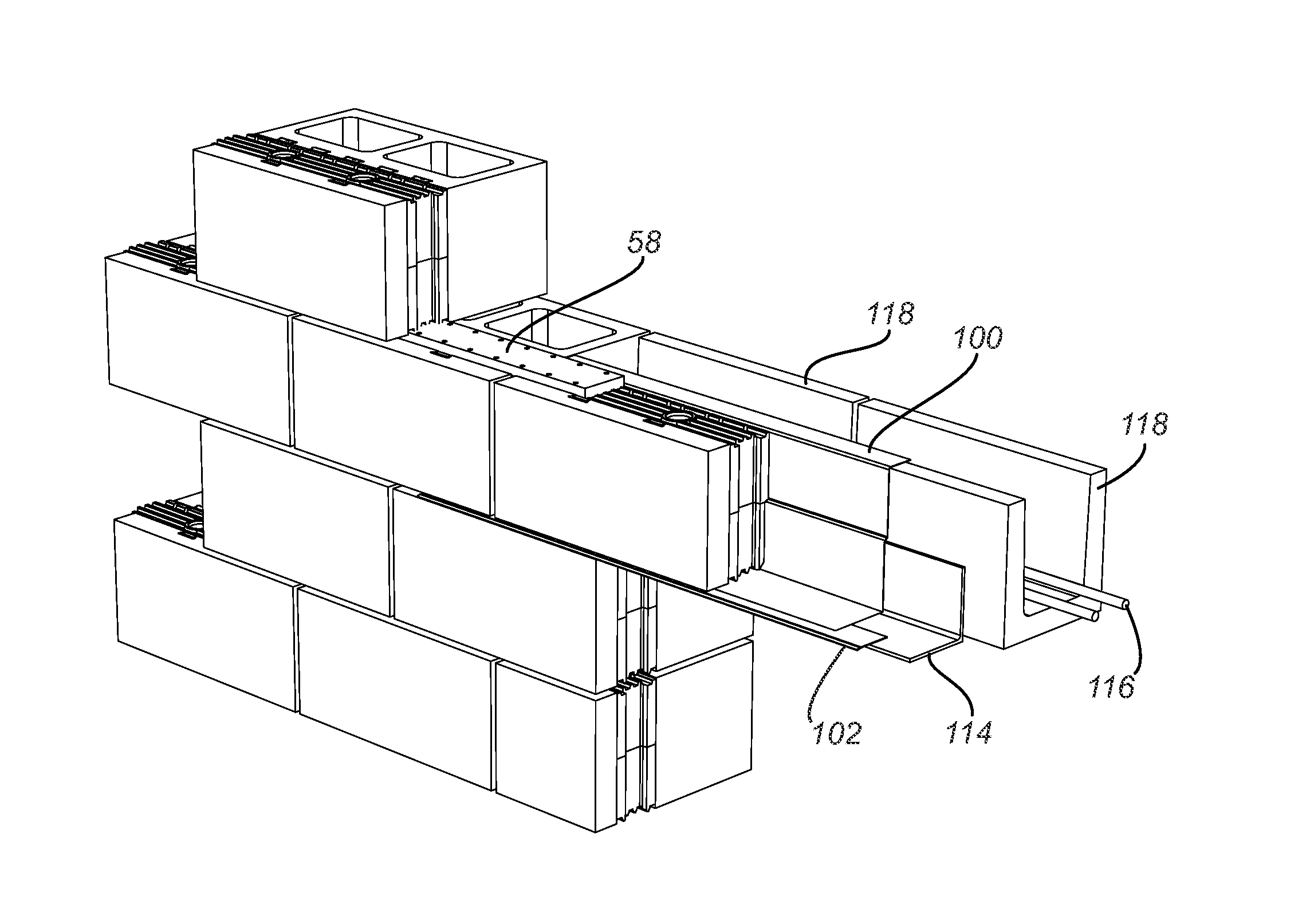
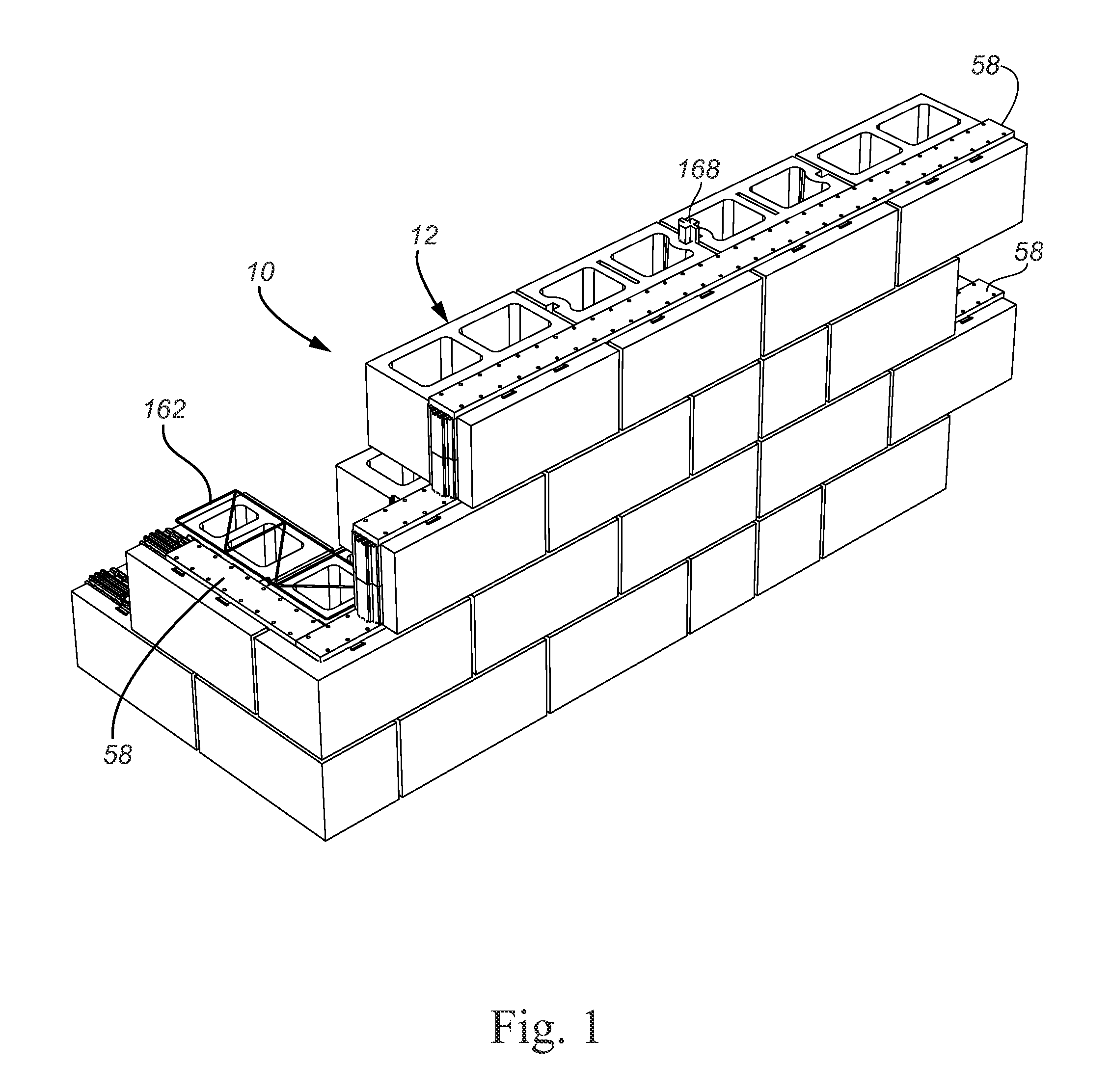
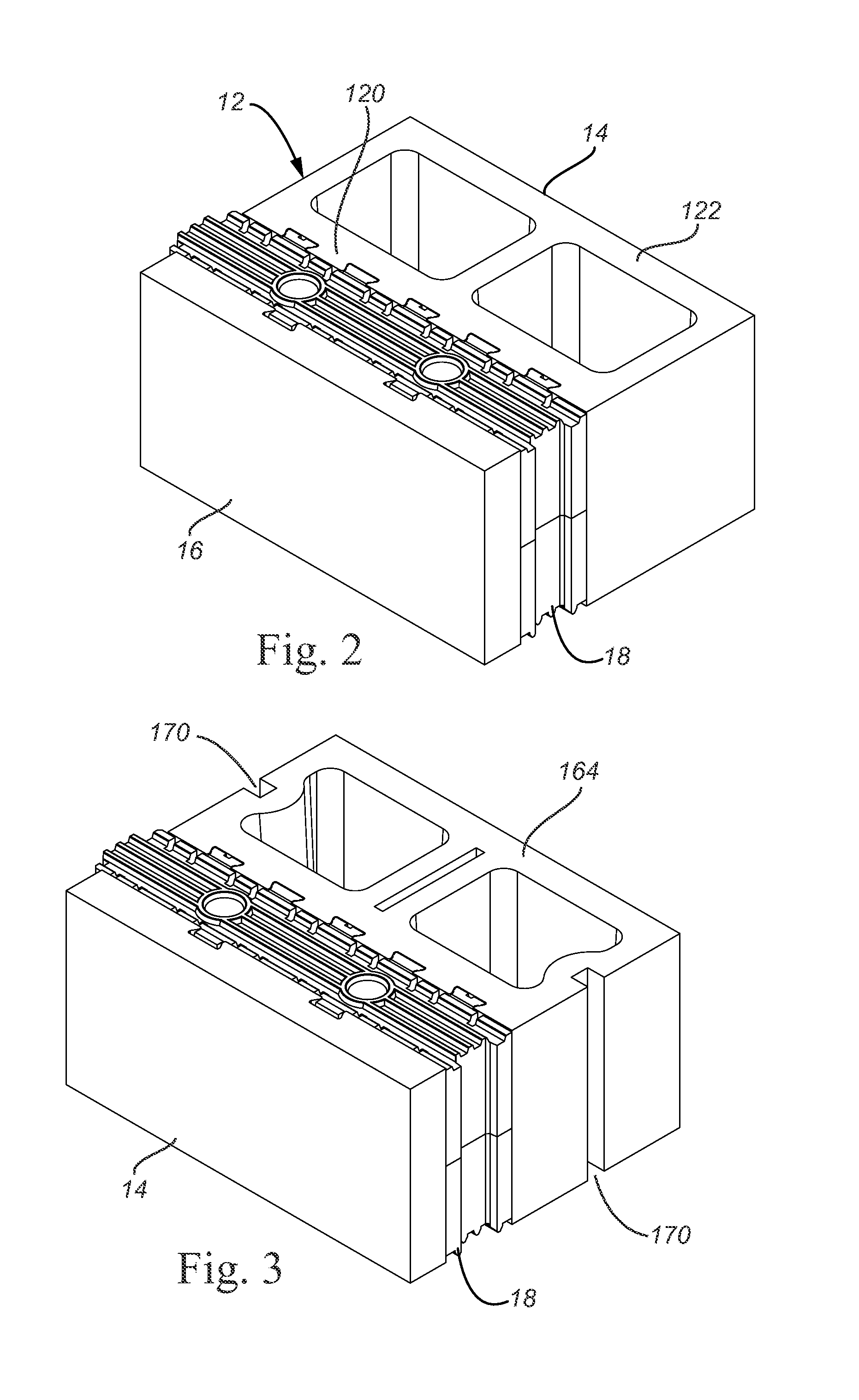
[0041]A basic block wall assembly 10 of a first embodiment of the insulated block system of this invention is depicted in FIG. 1. It includes an insulated stretcher block sub-assembly 12 (also shown in FIG. 2), together with other blocks, reinforcement and gasket material further described below.

[0042]Each insulated block assembly is assembled from three components, a structural...


PUM

PropertyMeasurementUnit
shapesaaaaaaaaaa
thermal insulationaaaaaaaaaa
shapeaaaaaaaaaa

Abstract

A insulated masonry wall system having insulation blocks between structural and face blocks to provide structures that are strong, inexpensive, avoid thermal bridges, and resist transmission of heat. The walls are attractive and versatile, and an enormous variety of decorative face members may be utilized. The face blocks are attached to the structural blocks to prevent facing materials from falling even if fire destroys the insulation blocks between the structural blocks and the facing. The system resists water penetration and effectively drains water that does penetrate any portion of the system.

Description

CROSS REFERENCE TO RELATED APPLICATION[0001]This application claims priority to U.S. Provisional Patent application Ser. No. 61 / 791,187 for “Insulated Block Wall System,” filed Mar. 15, 2013, which is incorporated herein by reference.FIELD OF THE INVENTION[0002]This patent relates to concrete and other masonry blocks, walls and other structures and, more specifically, to such structures that contain insulation and utilize facing materials.BACKGROUND OF THE INVENTION[0003]Masonry walls and similar structures have been made with a wide variety of construction materials and methods and therefore exhibit a large number of different characteristics. Among such walls, precast concrete block walls are well known. While precast concrete block or CMU (concrete masonry unit) walls are inexpensive and strong, conventional such walls provide relatively little resistance to heat transmission, may drain water poorly and are often unattractive.SUMMARY[0004]The terms “invention,”“the invention,”“th...

Claims


Application Information

Patent Timeline
Patent Type & Authority Applications(United States)
IPC IPC(8): E04C1/41E04C1/39E04B2/18
CPCE04C1/41E04C1/397E04B2/18E04B2/26E04B2002/0234E04B2002/0236E04B2002/0247E04B2002/0252E04B2002/0276E04B1/388E04B1/04E04B1/043E04B1/7629E04B1/78E04B2/14E04B2001/7679E04B2002/0256E04B2103/02E04B2103/04E04F13/0832E04F13/14
Inventor BROWNING, LEONARDLUNDELL, ROBERT J.BELIVEAU, STEPHANE
Owner OLDCASTLE ARCHITECTURAL
Why Eureka
Try Eureka