
Interchangeable inlet protection systems for air intakes of aircraft engines and related method

a technology for air intake protection and aircraft engines, which is applied in the direction of machines/engines, filtration separation, separation processes, etc., can solve the problems of increasing the vulnerability of engine parts to damage from small foreign particles, premature wear of engine components, and increasing maintenance costs

Inactive Publication Date: 2014-09-18
DONALDSON CO INC
View PDF2 Cites 29 Cited by
  • Summary
  • Abstract
  • Description
  • Claims
  • Application Information

AI Technical Summary

Benefits of technology

This patent describes an invention related to air filtration systems for aircraft engines. The invention includes a removable panel that filters air before it enters the engine. The panel has a unique shape that matches the shape of the aircraft, with a skin and a plurality of particle separators attached to the skin. The panel also has an opening that allows for the filtered particles to be discharged directly from the panel. Another aspect of the invention is a barrier filter system that includes two removable panels, one of which has barrier filter media and the other of which has particle separators. The system also includes a torque tube that supports the bypass panel. Various refinements and combinations of these features are also described. The technical effects of the invention include improved air quality for the engine, reduced fuel consumption, and improved performance and reliability.

Problems solved by technology

Some known compressors and turbines are designed with small clearances between moving parts that maximize efficiency, but which also increase vulnerability to damage of engine parts from small foreign particles.
Contaminants in intake air, even in a small amount or of a very small size, may cause premature wear on engine components, increase maintenance costs, and degrade operational performance and reliability.
Aircraft are exposed to contaminants when operating at low altitudes where air is frequently contaminated with material from the ground, such as sand and dust.
This problem may be aggravated for helicopters due to rotor downwash and prolonged low-altitude operation.
However, such systems are not completely satisfactory.

Method used


Image

  • Interchangeable inlet protection systems for air intakes of aircraft engines and related method
  • Interchangeable inlet protection systems for air intakes of aircraft engines and related method
  • Interchangeable inlet protection systems for air intakes of aircraft engines and related method

Examples


Embodiment Construction

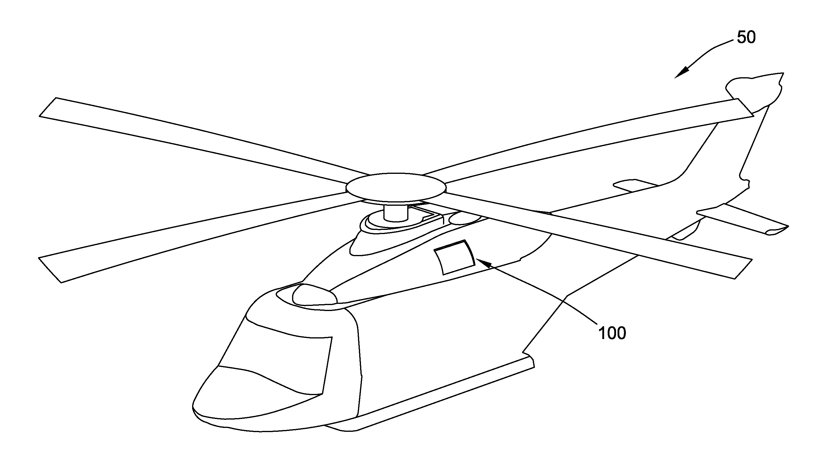
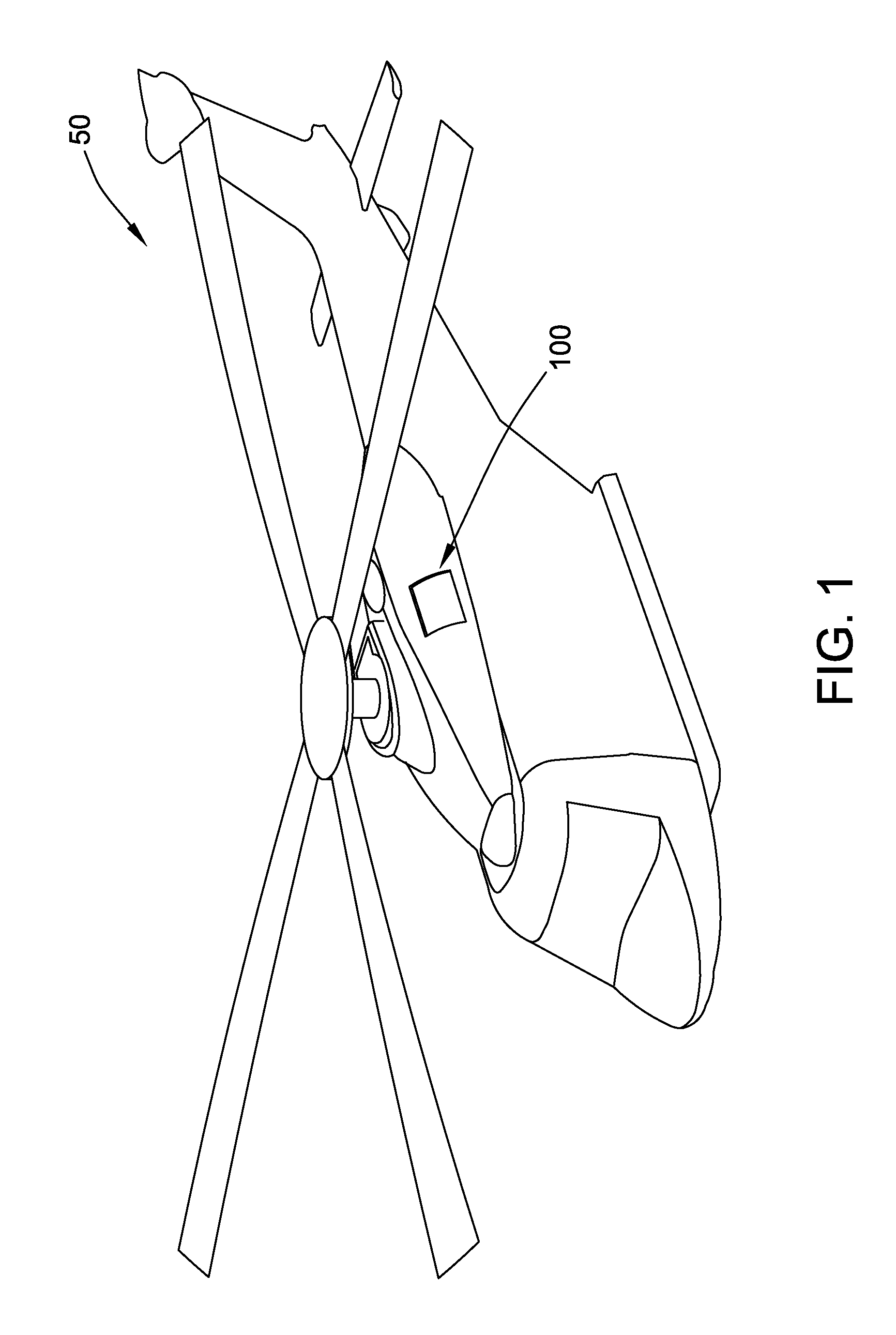
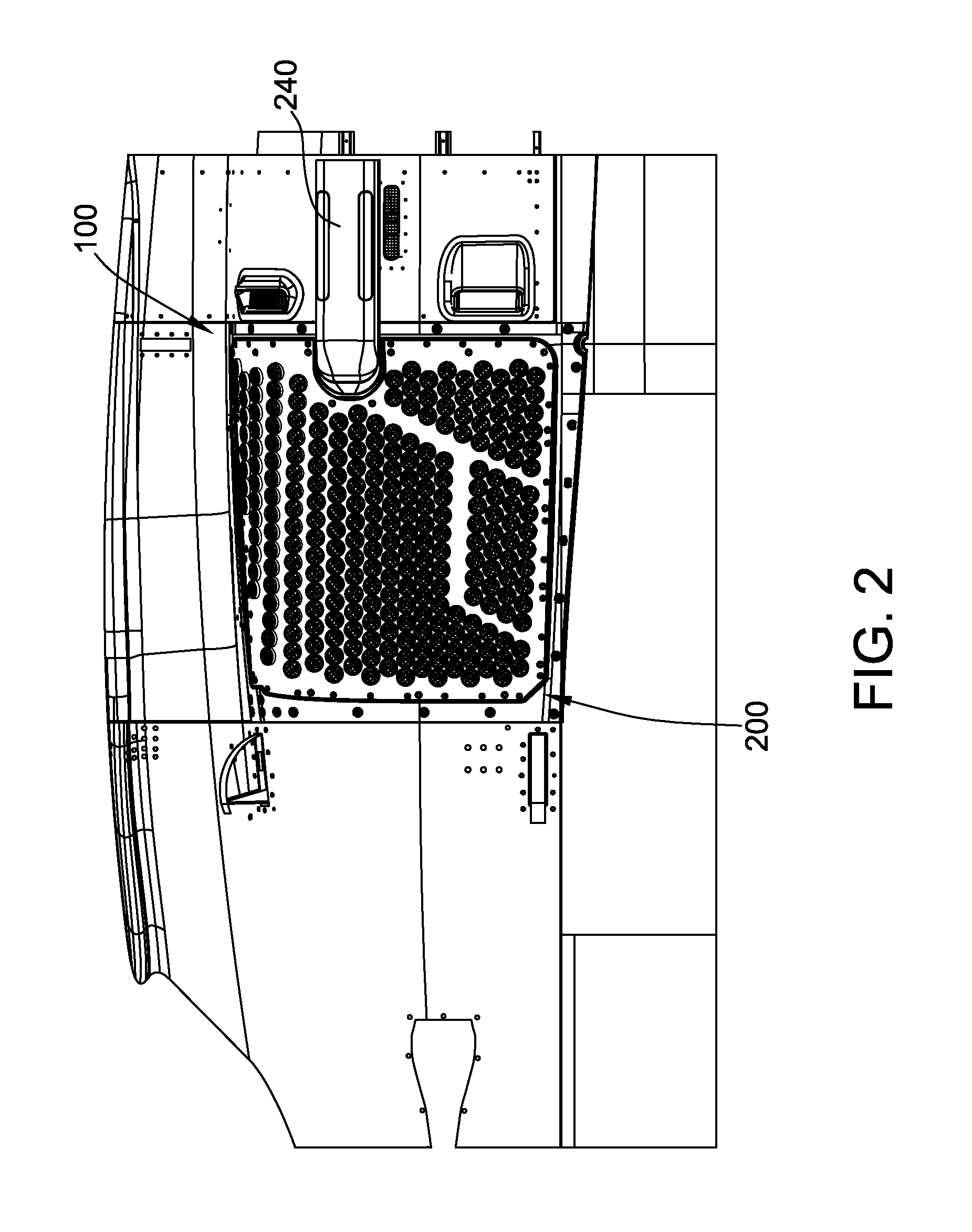
[0034]With reference to FIG. 1, an aircraft is shown and generally indicated at 50. The aircraft includes an inlet protection system 100. The inlet protection system 100 generally includes a particle separator panel 200, as shown in FIG. 2, and interchangeably, a barrier filter panel 300, as shown in FIG. 10.

[0035]With reference to FIGS. 2 and 3, the particle separator panel 200 includes a plurality of particle separators 210. At least a portion of the particle separators 210 are mounted in a composite body 220 and are aligned in rows extending from front to back along the body. In this embodiment, the body 220 is generally curved front to back and top to bottom. A D-shaped discharge opening 222 is located along an aft section of the body 220 at a height location above the midpoint of the body.

[0036]The body includes an inner skin 224, an outer skin 226, and a perimeter skin 228 connecting the inner and outer skins. A cavity 230 is defined within the body 220, between the inner skin...


PUM

PropertyMeasurementUnit
face velocityaaaaaaaaaa
air pressureaaaaaaaaaa
torsional rigidityaaaaaaaaaa

Abstract

An inlet protection system for filtering air prior to entry into an air intake of an engine of an aircraft includes interchangeably a particle separator panel and a barrier filter panel. The barrier filter panel is adapted to be mounted conformal to the contour of the aircraft and to be interchangeable with the particle separator panel. The particle separator panel has an outer skin and a plurality of particle separators. The outer skin has an opening disposed along a portion of it to discharge filtered particles from within the removable panel directly outward therefrom.

Description

FIELD[0001]The field of this disclosure relates generally to air inlet protection systems for aircraft and related methods, and more particularly, to inlet protection systems for aircraft engine air intakes and to related methods.BACKGROUND[0002]An engine for aircraft propulsion requires intake air that is free from contaminants to provide for efficient combustion and avoid damage to internal engine components. Some known compressors and turbines are designed with small clearances between moving parts that maximize efficiency, but which also increase vulnerability to damage of engine parts from small foreign particles. Contaminants in intake air, even in a small amount or of a very small size, may cause premature wear on engine components, increase maintenance costs, and degrade operational performance and reliability. Aircraft are exposed to contaminants when operating at low altitudes where air is frequently contaminated with material from the ground, such as sand and dust. This p...

Claims


Application Information

Patent Timeline
Patent Type & Authority Applications(United States)
IPC IPC(8): B64D33/02F02C7/055
CPCF02C7/055B64D33/02B64D2033/0246Y02T50/60B64D2033/022
Inventor BOYCE, MARK EDWARD
Owner DONALDSON CO INC
Learn More