Electrical cabinet with improved heat dissipation

a technology of electric cabinets and heat dissipation pipes, which is applied in the direction of lighting and heating apparatus, modifications by conduction heat transfer, and domestic cooling apparatus, etc. it can solve the problems of extreme heat-sensitive equipment, unsuitable for assembly installation, and increased the risk of filtering system blockag

Active Publication Date: 2014-09-18
SCHNEIDER ELECTRIC IND SAS
View PDF11 Cites 26 Cited by
  • Summary
  • Abstract
  • Description
  • Claims
  • Application Information

AI Technical Summary

Problems solved by technology

Furthermore, the equipments that are not very sensitive to heat and are able to operate at high temperatures are thus mixed with extremely heat-sensitive equipments.
Furthermore, the greater the power of the cooling production systems or equipment is, the greater the risks of clogging of the filtering systems are.
In addition, this solution is not suitable for an assembly installation comprising cabinets which are juxtaposed or fixed against a wall or a framework (non-accessibility of the cabinet via the rear).

Method used


Image

  • Electrical cabinet with improved heat dissipation
  • Electrical cabinet with improved heat dissipation
  • Electrical cabinet with improved heat dissipation

Examples


Embodiment Construction

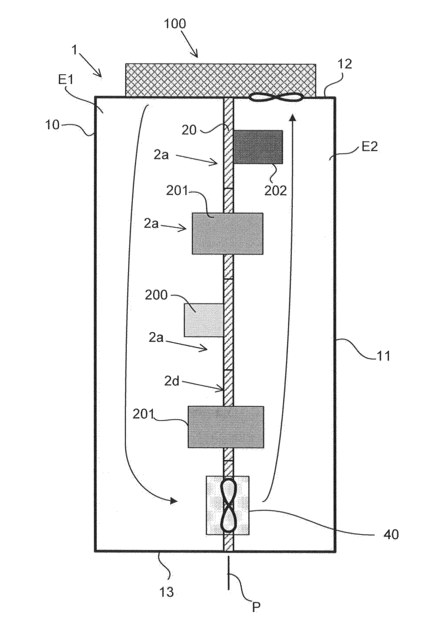
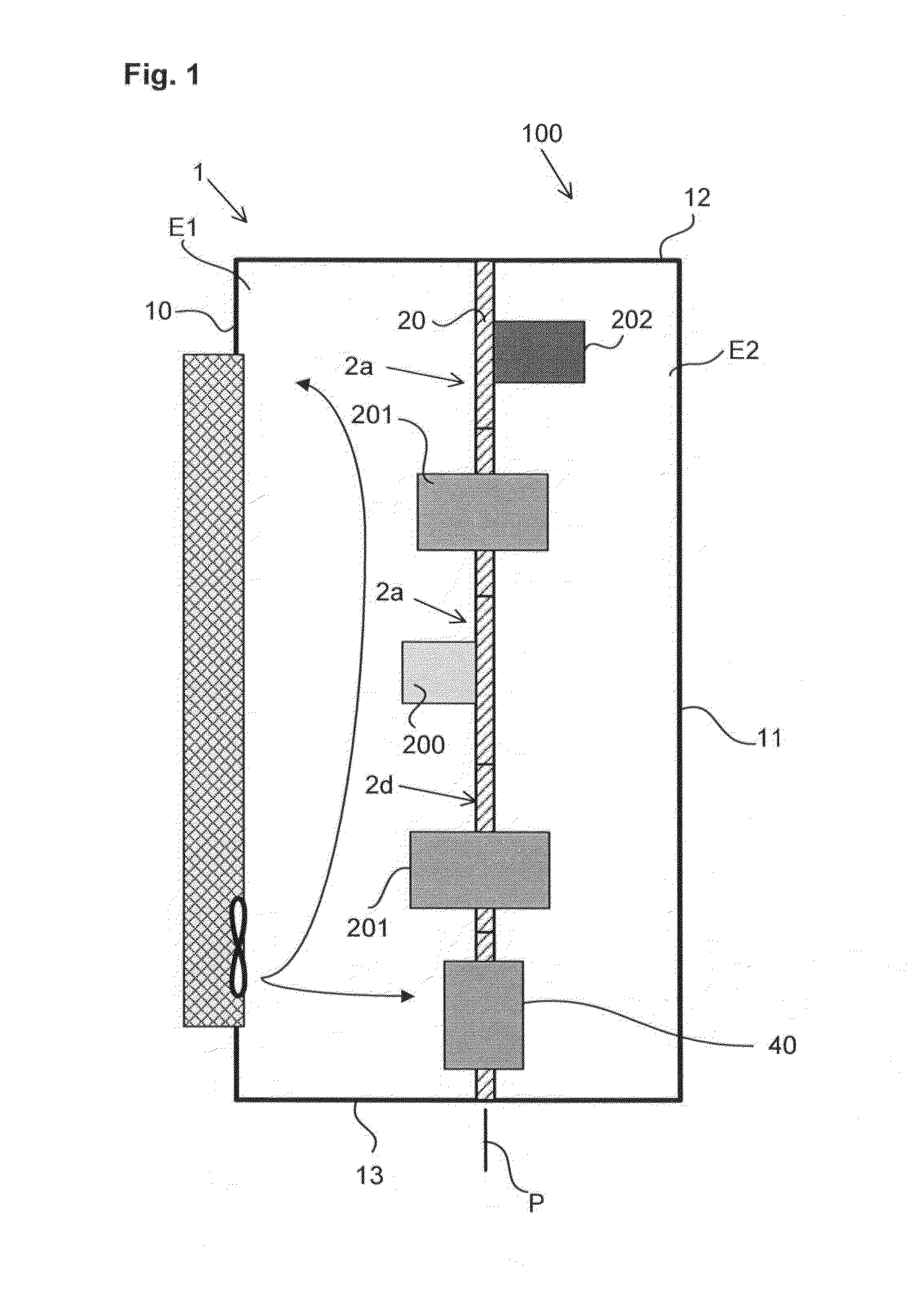
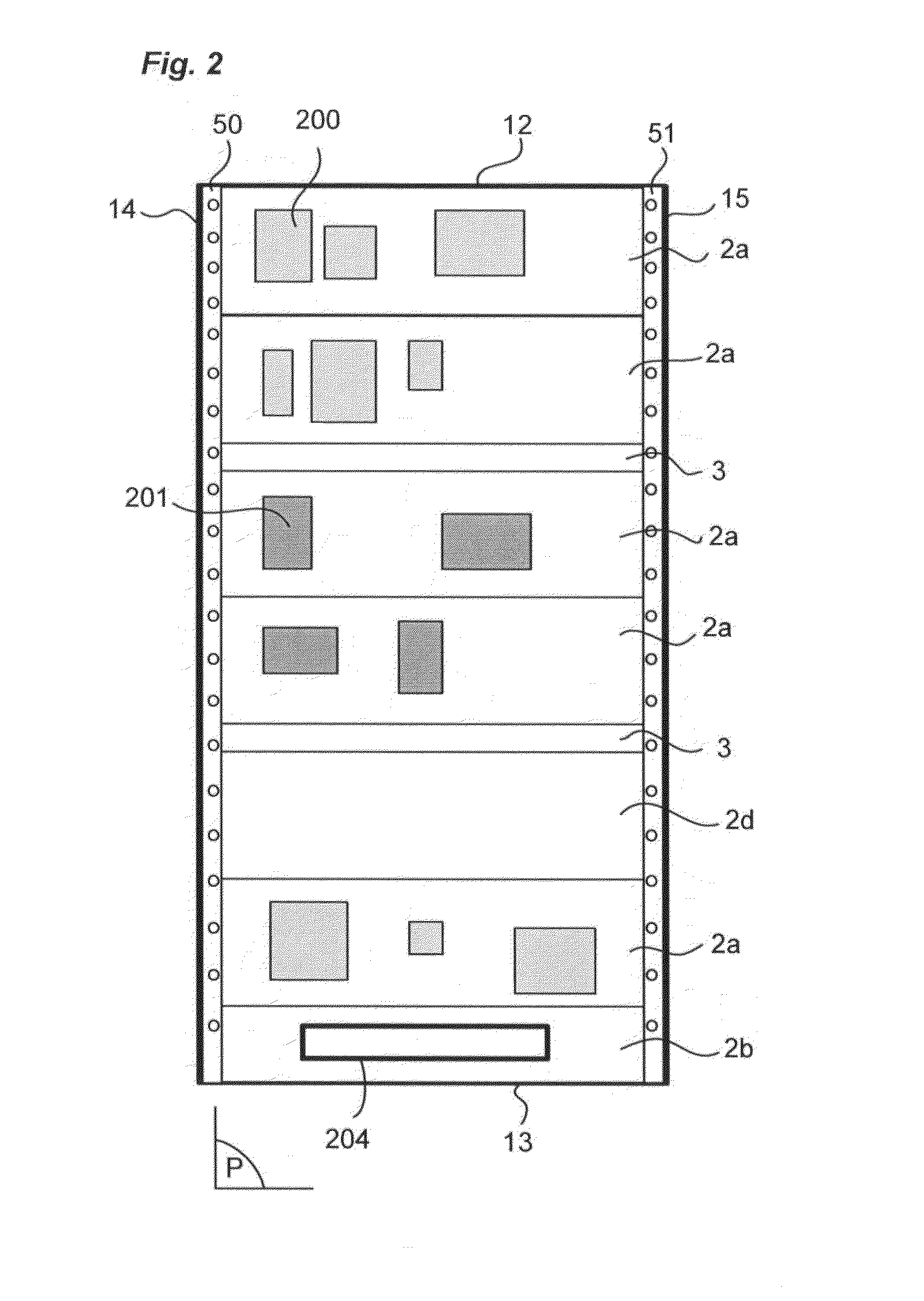
[0024]The invention relates to an electric cabinet 1. The electric cabinet 1 is preferably of rectangular shape. Naturally, a cabinet that is cylindrical or has a circular cross-section or a cross-section of a different shape could quite naturally be envisaged. This principle also applies to any electric panel the protective enclosure of which is formed by the frame of the equipment with complex shapes. In the remainder of the description, an electric cabinet of rectangular shape will be dealt with. The electric cabinet thus comprises a front panel 10, a rear panel 11, a top panel 12, a bottom panel 13 and two side panels.

[0025]The front panel 10 of the electric cabinet 1 for example comprises a door for access to the inside of the cabinet.

[0026]The electric cabinet 1 of the invention can in particular be tightly sealed, for example in compliance with the IEC 60529 standard with an ingress protection rating IP55. The heat dissipation solution described below is particularly suitable...


PUM


Abstract

The invention relates to an electric cabinet (1) comprising a front part and a rear part and designed to receive electric functional units (2a), said electric cabinet (1) also comprising a separating partition (20) delineating:
    • a first cold thermal area formed by a first space (E1) located at the front part of the cabinet, and
    • a second hot thermal area formed by a second space (E2) located at the rear part of the cabinet.
The electric cabinet (1) comprises a cooling and regulating device of the temperature of the first and second spaces E1, E2, said device comprising:
    • a cooling source (100) positioned in contact with the first space (E1) to cool the latter;
    • heat exchange means (40) enabling cold air to flow between the first space (E1) and the second space (E2).

Description

BACKGROUND OF THE INVENTION[0001]The invention relates to an electric cabinet with improved heat dissipation. The electric cabinet comprising a front part and a rear part is designed to receive electric functional units each comprising electric apparatuses. Said electric cabinet also comprises a separating partition delineating a first cold thermal area and a second hot thermal area. The first area is formed by a first space located at the front part of the cabinet, said cold area being designed to receive electric apparatuses or parts of apparatuses which do not heat or which heat very little. The second thermal area is formed by a second space located at the rear part of the cabinet, said cold area being designed to receive apparatuses or parts of apparatuses which are subject to temperature rises.STATE OF THE PRIOR ART[0002]It is known to install electric equipment units on a support frame fixed to the rear of an electric cabinet. Cooling is then performed in traditional manner v...

Claims


Application Information

Patent Timeline
Patent Type & Authority Applications(United States)
IPC IPC(8): H05K7/20
CPCH05K7/202H05K7/20145H02B1/565H05K7/20518H05K7/206H05K7/20909
Inventor AGNAOU, ABDERRAHMANEWASNER, OLIVIERPERRIN, ALAINSOCQUET, DOMINIQUELAYE, JEROMELEPRETRE, PASCAL
Owner SCHNEIDER ELECTRIC IND SAS
Why Eureka
Try Eureka