Methods and apparatus for indoor air contaminant monitoring

a technology of indoor air and contaminant monitoring, applied in ventilation systems, heating types, instruments, etc., can solve the problems of increasing the sensed air contaminant level in the controlled room or space, increasing the cost of laser and detector systems that are centralized, and increasing the level of air contaminants not being properly diluted, so as to improve indoor air quality, reduce airflow, and increase ventilation

Active Publication Date: 2014-09-18
AIRCUITY
View PDF1 Cites 83 Cited by
  • Summary
  • Abstract
  • Description
  • Claims
  • Application Information

AI Technical Summary

Benefits of technology

[0033]Exemplary embodiments of the invention provide methods and apparatus for determining indoor air contaminant levels independent of outdoor contaminant levels. In an exemplary embodiment, a system uses indoor air contaminant levels to create a dilution ventilation command signal and / or an outside airflow command signal. A dilution ventilation command signal is defined as an airflow command signal that can be used to vary, at least partially, the supply airflow rate into a monitored room or space based on sensed indoor air contaminant parameter information. The purpose of this control signal is to appropriately increase ventilation when air contaminant levels in a space or building are too high, typically to improve indoor air quality, and to decrease airflow levels, typically to save energy, when both the number of occupants in a space is reduced and the air is relatively clean of contaminants.
[0034]An outside airflow command signal is defined as an airflow command signal that can be used to vary, at least partially, the outside airflow into a building or air handling unit based on potentially multiple factors. These factors include, for example, the sensed air quality parameter information inside the building, the sensed air quality parameter information outside the building, the comparative levels of inside and outside sensed air quality parameters, the amount of free cooling to optimize energy efficiency and comfort, and the amount of outside airflow required to meet recommended guidelines based on the real time or design occupancy of for example the entire area of the building served by a particular return air handling unit, specific critical areas served by the return air handling unit, or areas served by the return air handling unit with varying occupancy. The purpose of this control signal is to balance energy savings from free cooling and demand control ventilation with providing enhanced indoor air quality through increased dilution of internal contaminants and preventing the excessive use of outside air when it is “dirty” or has excessive levels of air contaminants.
[0038]Exemplary embodiments of the invention can provide systems and methods for creating indoor air contaminant measurements independent and unaffected by outdoor air contaminants thereby preventing dilution ventilation and outside airflow control from becoming latched up at high flow rates due to high outdoor levels of air contaminants. One embodiment using a multipoint air sampling system provides uniquely high accuracy to make this application possible since many differential measurements such as between room air contaminant levels and the supply air contaminant levels are made with the same sensor substantially reducing normal sensor errors that would typically be magnified when taking the difference between two different sensors.

Problems solved by technology

These star configured systems are sometimes called octopus-like systems or home run systems and may use considerable amounts of tubing.
The expensive part is the laser and detector systems that are centralized.
Although high CO2 levels are often associated with poor indoor air quality levels, it is not the level of CO2 itself that creates the discomfort and symptoms associated with poor indoor air quality but instead the associated rise in air contaminants that are not being properly diluted.
One known problem with sensing the level of indoor air contaminants such as for monitoring or for the control of dilution ventilation, particularly for such contaminants that are found commonly in outside air such as particles, CO, TVOC's or others, is that if the outside air concentrations become high enough, increasing the airflow volume of outside air or the supply air into a controlled area or room for purging or dilution ventilation will actually increase the sensed air contaminant levels in the controlled room or space.
This can potentially create a negative feedback situation when the inside dilution ventilation threshold levels are exceeded forcing the outside airflow levels and or room supply air flow levels to their maximum level.
Depending on the level of design capacity of the HVAC system, the capacity of the air handling system could be exceeded in this latch-up situation, causing a degradation of HVAC system control.
The problem with return air handling units is that the contaminant that may be generated in a given space will be returned to the air handling units and some percentage of this contaminant will be then mixed with the outdoor air and then fed via the return air handling unit's supply air back into the original room plus into other rooms.
However, if the sources of contaminant can be large, the period of release potentially long, or the number of spaces where the contaminant is generated can be a reasonable percentage such as over 10%, then the simple differential measurement method will likely produce inaccurate results.
It can also cause significant problems when used for dilution ventilation when these conditions may be present.
Thus the total amount of indoor air contaminant in the room will not be accurately calculated since it includes both the amount instantaneously generated in the space plus the amount returned to the space.
Unfortunately this is not sufficient for proper dilution ventilation control.
However, in this situation the background levels of the contaminant could grow quite high due to insufficient outside air yet it would not be detected by the simple differential measurement method.
As shown for example by U.S. Pat. No. 8,147,302 B2, this issue of finding the true level of indoor air contaminants independent of the outdoor air contaminant in a space is also not even recognized as a problem in the prior art.
Even if the above patents disclosed how to determine the return air fraction, it is still not enough.
However even this is still not a sufficient method.

Method used


Image

  • Methods and apparatus for indoor air contaminant monitoring
  • Methods and apparatus for indoor air contaminant monitoring
  • Methods and apparatus for indoor air contaminant monitoring

Examples


Embodiment Construction

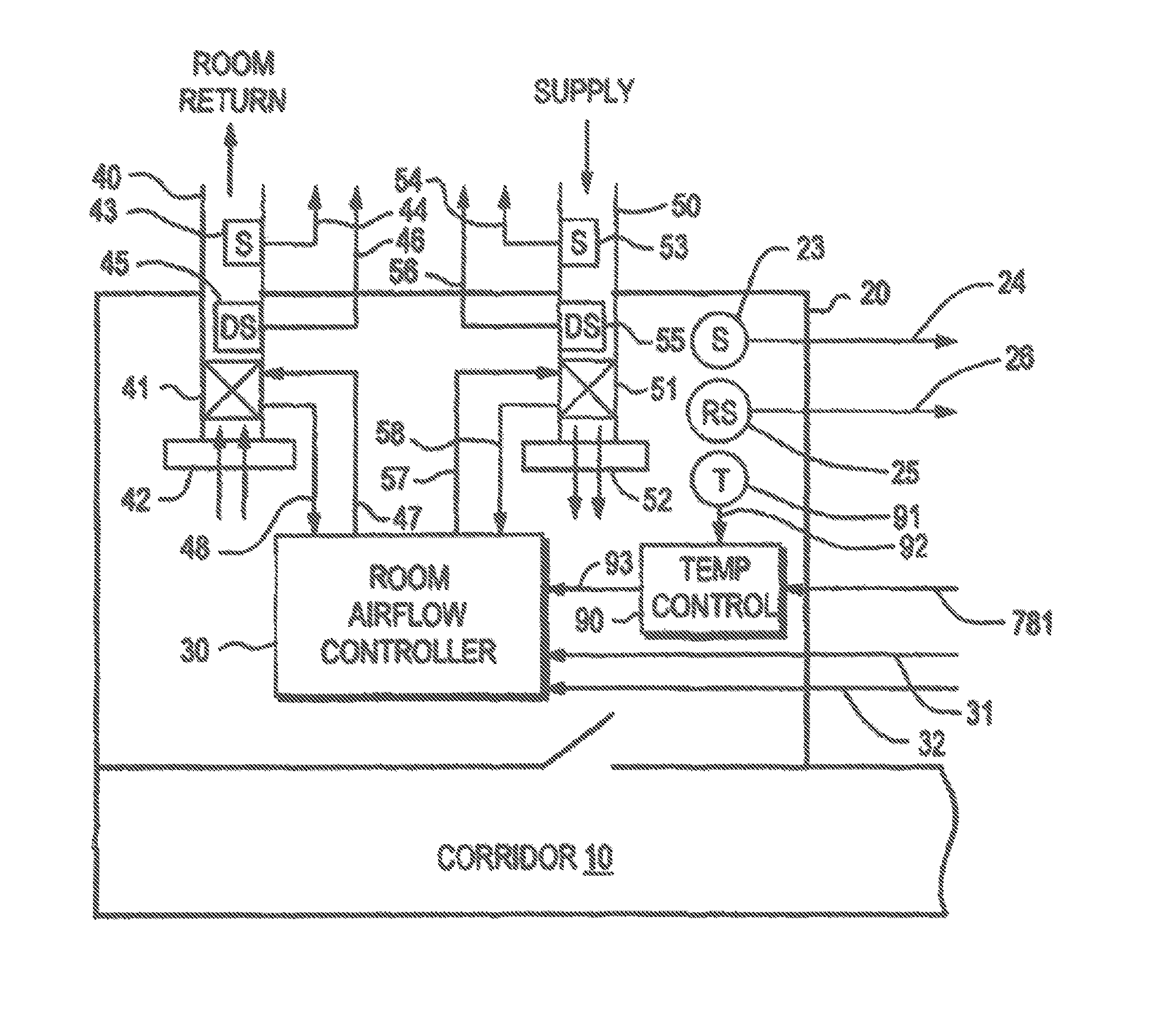
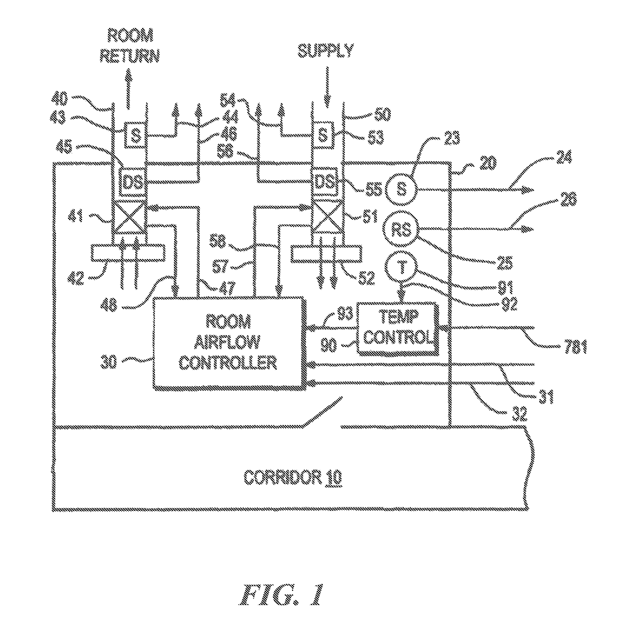
[0048]FIG. 1 show a typical monitored environment or room 20 that has doors that may enter a corridor 10 that may also be monitored. Although the diagrams show one room and a corridor, it is understood that exemplary embodiments of the invention may be used with just one room or space or monitored area, or any plurality of rooms or spaces including corridors or other adjacent spaces that are also being monitored, such as for example, two or more rooms, or one corridor plus one or more spaces. Note also that, although the illustrative environments are enclosed within walls, monitored environments, spaces or areas may also comprise a section or area of a room having no walls or partitions around it. Thus, there may be multiple monitored environments within one physical room. Alternatively, multiple physical rooms may also constitute one environment or space. Typically, the environment 20 will also be an area that is fed by one or more supply airflow control devices 51. Potentially a r...


PUM

PropertyMeasurementUnit
sampling timeaaaaaaaaaa
timeaaaaaaaaaa
particle sizeaaaaaaaaaa

Abstract

Methods and apparatus for determining indoor air contaminant levels independent of outdoor contaminant levels. In one embodiment, an infinite geometric series is used to compute a true indoor air contaminant level in a room.

Description

FIELD OF THE INVENTION[0001]Exemplary embodiments of the invention provide methods and apparatus for air contaminant monitoring involving the use of either multipoint air sampling systems or discrete local air quality parameter sensors to sense one or more of air contaminants and air parameters to determine the amount of indoor air contaminants present in a given indoor space independent of the level of outdoor air contaminants that are being pulled into the building when said indoor space is being supplied by an air handling unit referred to as a return air handling unit that at least partially recirculates some of the indoor air back into the given indoor space instead of exhausting all of this return air. The determined level of indoor air contaminants may be used for information purposes only or to generate control signals to increase the supply airflows into the indoor space, increase outdoor air levels into said air handler or for other building control purposes.[0002]Exemplar...

Claims


Application Information

Patent Timeline
Patent Type & Authority Applications(United States)
IPC IPC(8): G01N1/22
CPCG01N1/2205F24F7/08F24F11/0001F24F2011/0002F24F11/30F24F2110/50F24F11/62G01N1/2273Y02B30/70F24F11/74Y02B30/54
Inventor SHARP, GORDON P.
Owner AIRCUITY
Why Eureka
Try Eureka