
Concrete Anchor

Active Publication Date: 2014-09-18
OSTROBROD MEYER
View PDF33 Cites 18 Cited by
  • Summary
  • Abstract
  • Description
  • Claims
  • Application Information

AI Technical Summary

Benefits of technology

The present invention aims to improve the installation of concrete anchors and provide better protection for workers in the event of a fall. The invention includes an indicator that alerts the user if the anchor has been previously used to prevent a fall.

Problems solved by technology

There are, however, times when iron work or the like is not available and the lanyard or lifeline must be secured directly to a concrete slab.
To Applicant's knowledge, however, none has been satisfactory.
It has been found, however, that the patented anchor is not always reliable and can slip out of the bore if sufficient force is applied.

Method used


Image

  • Concrete Anchor
  • Concrete Anchor
  • Concrete Anchor

Examples


Embodiment Construction

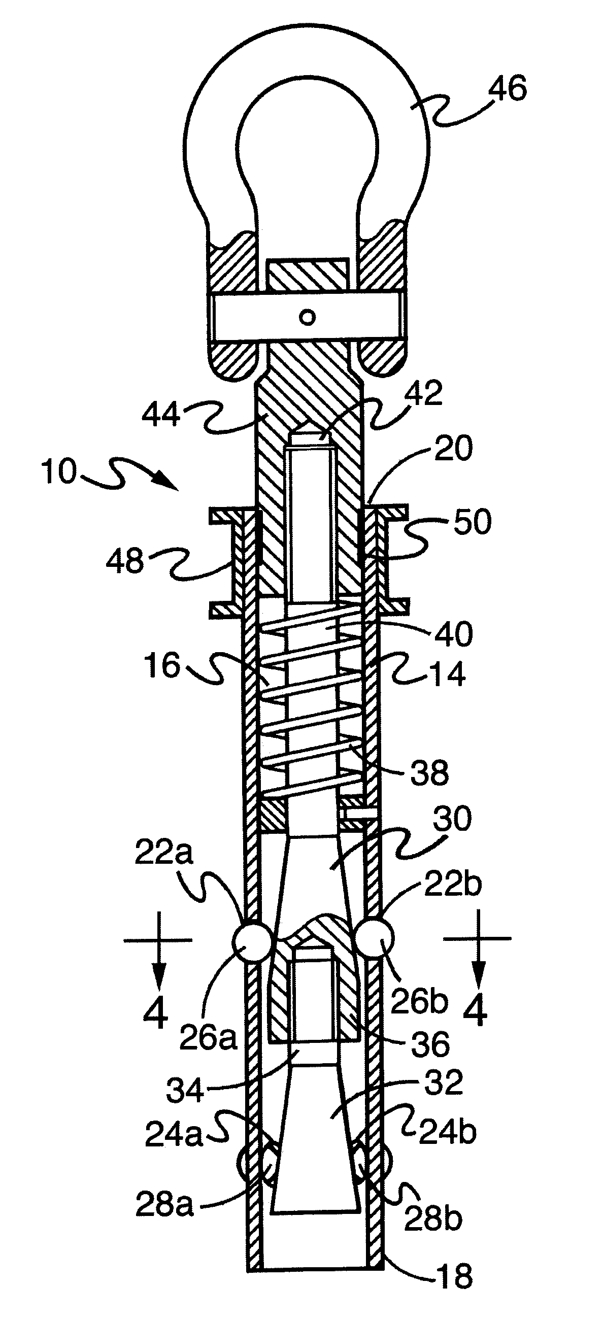
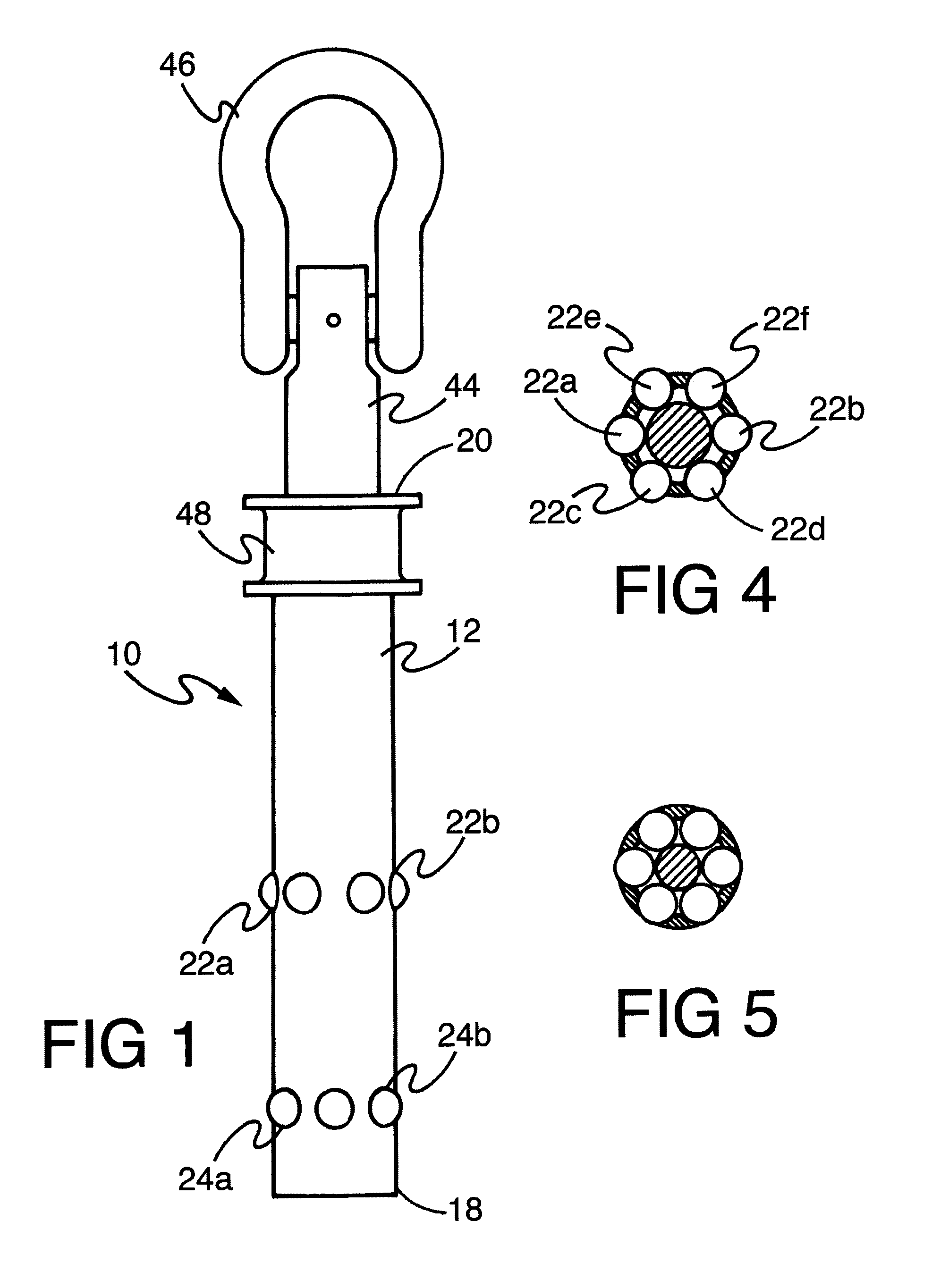
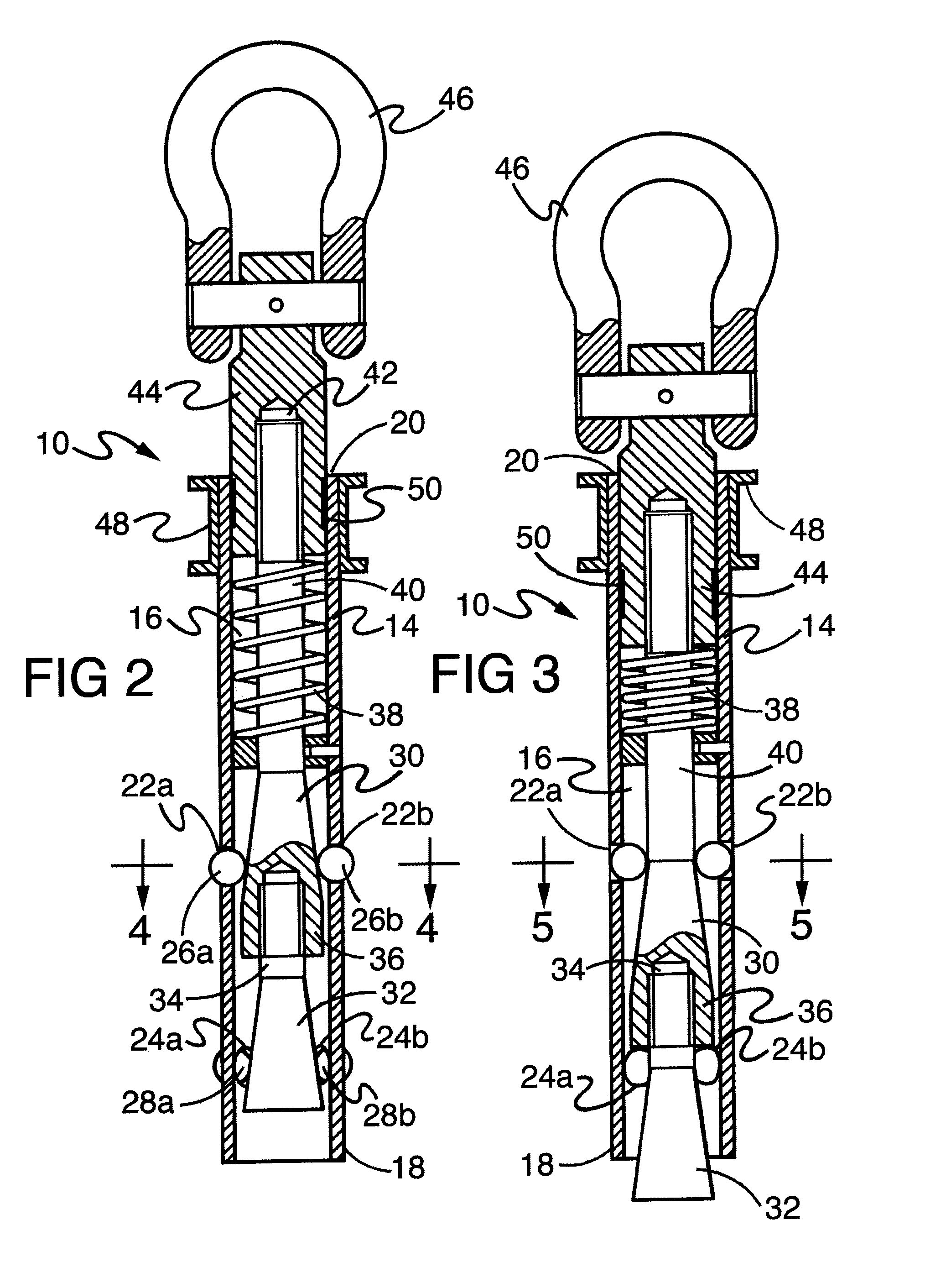
[0019]Referring now to the drawings in detail wherein like reference numerals have been used throughout the various figures to designate like elements, there is shown in FIG. 1 a concrete anchor constructed in accordance with the principles of the present invention and designated generally as 10. The anchor 10 is comprised of a substantially cylindrically shaped housing 12 having a substantially cylindrically shaped outer wall 14 and a substantially hollow interior 16. The housing 12 has a length defined by a lower end 18 and an upper end 20. As should be readily apparent to those skilled in the art, the outer dimensions of the housing 12 are such as to fit within a similarly shaped bore in the surface of a concrete slab.

[0020]The wall 14 has a plurality of openings therein such as shown at 22a and 22b and at 24a and 24b. In the preferred embodiment of the invention, there are six openings 22a-22f and six openings 24a-24f. The first set of six openings 22a-22f are arranged around th...


PUM


Abstract

A concrete anchor for securing the lanyard of a workman's harness to a fixed position on a concrete surface includes a cylindrical housing having an outer wall with openings therein and a rod that extends above the housing to which a harness can be attached. Hard metal balls within the housing are associated with each opening and are dimensioned so that a portion of each ball can pass through each opening but the entire ball can not pass therethrough. A pair of cones within the housing move the balls radially outwardly as the cones are moved upwardly by the rod which is spring biased upwardly. A visual marker carried by the rod normally lies within the housing but is visible from outside of the housing if said rod has moved up by a predetermined amount. This gives an indication that the anchor has been used.

Description

BACKGROUND OF THE INVENTION[0001]The present invention is directed toward a concrete anchor and, more particularly, toward a concrete anchor that is adapted to be connected the lanyard of a harness of a construction worker to help prevent injury to the worker in the event of a fall.[0002]During the construction or repair of buildings, bridges, road overpasses and other structures, workmen of various specialties frequently have to work at high elevations. To prevent injuries from falls, these workmen are provided with a harness and lanyard. Frequently, the lanyard is connected to a fall safety device such as described in U.S. Pat. No. 4,511,123 which issued to the present Applicant and which controls the decent and stops a worker from falling. In any event, the lanyard or the fall safety device must be secured to a fixed part of the structure. This can be directly to part of the iron work or to a horizontal life line such as shown in U.S. Pat. No. 6,640,727 which also issued to the p...

Claims


Application Information

Patent Timeline
IPC IPC(8): A62B35/00
CPCA62B35/0068E04G21/3276E04G21/329A62B35/0006E04G21/3204F16B7/025F16B7/1409F16B7/1463F16B13/045F16B13/08F16B13/0816F16B13/0825F16B13/0833F16B13/0858F16B13/0883F16B13/0891F16B21/165F16B13/10
Inventor OSTROBROD, MEYER
Owner OSTROBROD MEYER
Features
  • Generate Ideas
  • Intellectual Property
  • Life Sciences
  • Materials
  • Tech Scout
  • Unparalleled Data Quality
  • Higher Quality Content
  • 60% Fewer Hallucinations
Learn More