Lobed aperture radiant sensor

a radiant sensor and aperture technology, applied in the field of radiation sensors, can solve the problems of inconvenient remote location of the overhead console, hvac control module, and unsatisfactory field of view

Inactive Publication Date: 2014-09-18
KELSEY HAYES CO
View PDF0 Cites 5 Cited by
  • Summary
  • Abstract
  • Description
  • Claims
  • Application Information

AI Technical Summary

Problems solved by technology

Unfortunately, the overhead console location is inconveniently remote from the HVAC control module, which is integrated into the dashboard of the vehicle.
The field of view afforded by this location, however, is not ideal.

Method used


Image

  • Lobed aperture radiant sensor
  • Lobed aperture radiant sensor
  • Lobed aperture radiant sensor

Examples


Embodiment Construction

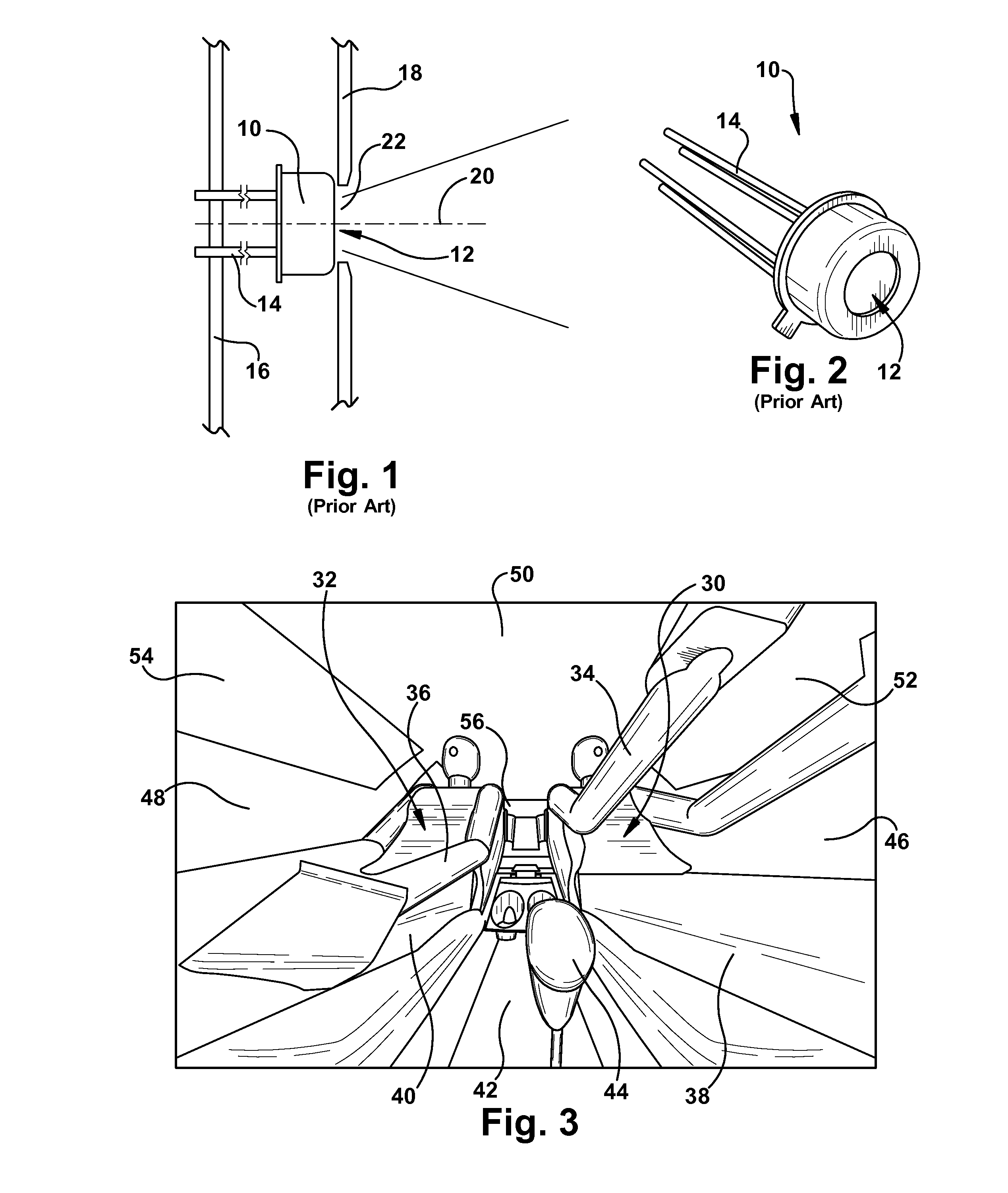
[0021]Vehicle climate control system may use a radiant sensor for measuring the temperature inside the vehicle cabin. FIGS. 1 and 2 show an example radiant sensor 10 that might be used for this purpose. The sensor may be the Melexis MLX90615 IR temperature sensor. The sensor has a generally cylindrical shape. A circular aperture 12 on the top of the sensor exposes the thermopile sensor element of the sensor to IR energy passing through the aperture, and four connection pins 14 on the bottom of the sensor provide a means of mounting the sensor while also electrically connecting it with other vehicle electronics.

[0022]The sensor 10 is mounted via its pins 14 on a printed circuit board 16 located within an HVAC control head, not separately shown. The connection pins 14 are soldered to circuit traces on the printed circuit board and thereby connected to a microcontroller and other electronics within the HVAC control head. An optical filter, not separately numbered, is contained within t...


PUM

PropertyMeasurementUnit
angleaaaaaaaaaa
radiant energyaaaaaaaaaa
infrared energyaaaaaaaaaa

Abstract

A radiant sensor includes a modified, e.g. lobed, aperture for modifying the sensor response to heat sources with its field of view to achieve a mean radiant temperature measurement.

Description

CROSS REFERENCE TO RELATED APPLICATIONS[0001]This application claims priority to and the benefit of U.S. Provisional Application Ser. No. 61 / 779,077, filed Mar. 13, 2013, entitled LOBED RADIANT SENSOR, assigned attorney docket number BCS-022083 US PRO. The above-identified provisional application is incorporated herein by reference in its entirety for all purposes.FIELD OF THE INVENTION[0002]The present invention is directed to radiant sensors and is more particularly directed to a radiant sensor with a modified aperture for use in vehicle cabins.BACKGROUND[0003]The heating ventilating and air conditioning (HVAC) systems used in motor vehicles today often include electronic, closed-loop control of the temperature within the vehicle. In some systems, temperature control is augmented with humidity control and more sophisticated evaluation of heat loading and relative conditions inside and outside of the vehicle cab. In such systems, a unified ‘comfort level’ control may be provided in...

Claims


Application Information

Patent Timeline
Patent Type & Authority Applications(United States)
IPC IPC(8): G01J5/00
CPCG01J5/0025B60H1/00742G01J5/06G01J5/12G01J5/0831Y10T29/49769
Inventor RUITER, TODD
Owner KELSEY HAYES CO
Why Eureka
Try Eureka