Fluid Flow Valve

Inactive Publication Date: 2014-09-18
CARTEN CONTROLS
View PDF10 Cites 5 Cited by
  • Summary
  • Abstract
  • Description
  • Claims
  • Application Information

AI Technical Summary

Benefits of technology

[0012]Accordingly, it is a principal object of the present invention to provi

Problems solved by technology

Known conventional valves for such applications as the latter mentioned above suffer from the disadvantage that the configuration thereof permits impurities to enter the gases passing through them.
Furthermore, the sealing disks or plugs of such valves are attached by means of bolts having heads which project into the flow path, disrupting the flow and/or leading to contaminant particle generation.
A further disadvantage of some known conventional valves is that, when they are moved to a closed position, there is wiping action between sealing members, which wiping action is provided to wipe debris from the faces of the sealing members.
However, such a skilled artisan would be disappointed for at least the following reasons, namely insufficiently achievable flow coefficients (Cv) of the design, impurity contribution levels, weight and size of the valve.
For example, it has been experimentally determined that simply increasing the diameter of the inlet and outlet pipe ends does not guarantee an increase in the Cv.
Similarly, simply increasing the diameter of the seat size does not achieve the d

Method used


Image

  • Fluid Flow Valve
  • Fluid Flow Valve
  • Fluid Flow Valve

Examples


Embodiment Construction

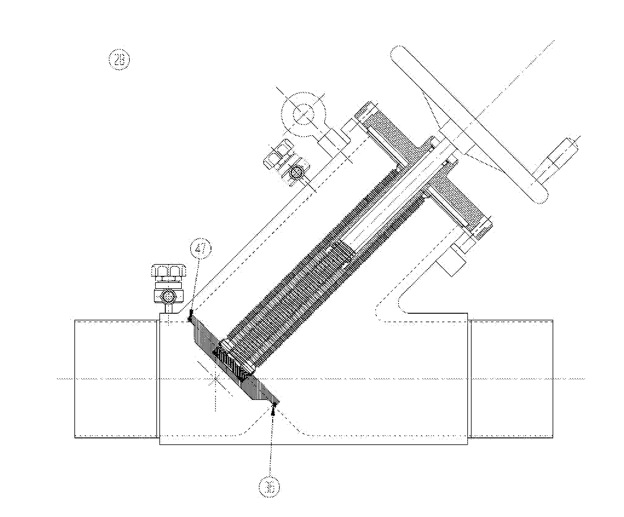
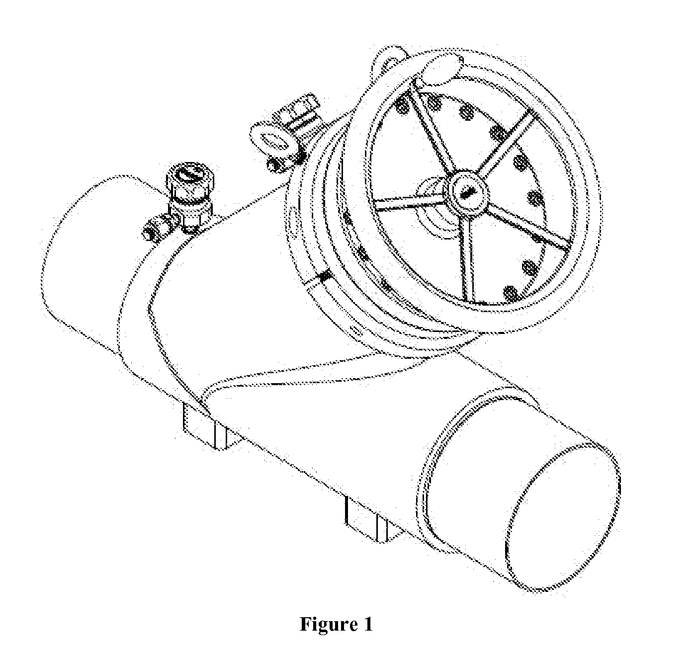
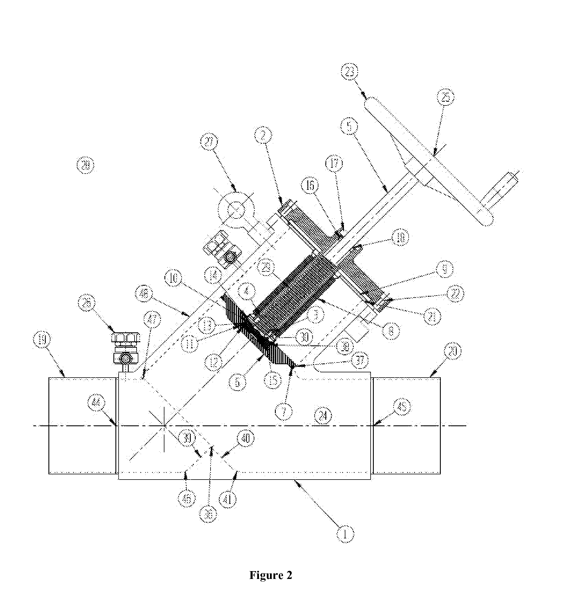
[0030]Reference should now be made to the drawing figures, on which similar or identical elements are given consistent identifying numerals throughout the various figures thereof, and on which parenthetical references to figure numbers direct the reader to the view(s) on which the element(s) being described is (are) best seen, although the element(s) may be seen also on other views. It is also noted that the subject matter of U.S. Pat. No. 5,385,334 is incorporated herein by reference in its entirety.

[0031]Generally speaking, the figures in greater detail show, and the following text discloses, a fluid flow valve that comprises a body comprising a body inlet, a body outlet, a housing; a movable member positioned within the housing and having a lower face, the movable member being movable between a position spaced from a position in said body when said valve is in an open position and movable to a sealing position when said valve is in a closed position; an elongated channel between ...


PUM


Abstract

A fluid flow valve, the fluid flow valve having a body comprising a body inlet, a body outlet, and a housing; a movable member positioned within the housing and having a lower face, the movable member being movable between a position spaced from a position in said body when said valve is in an open position and movable to a sealing position when said valve is in a closed position; an elongated channel between the body inlet and the body outlet, wherein the channel has at least an essentially uniform internal diameter, with the exception of a raised seat therein, from the body inlet to the body outlet, and a raised seat positioned within the channel, wherein the lower face of the movable member is in the sealing position when positioned against the raised seat and a lip formed in the body.

Description

BACKGROUND OF THE INVENTION[0001]1. Field of the Invention[0002]The present invention relates to valves generally and, more particularly, but not by way of limitation, to a novel bellows fluid flow valve which is particularly useful in applications in which maintaining the purity of the fluid passing through the valve is critical.[0003]2. Background Art[0004]Fluid flow valves are widely used in a variety of applications for controlling the flow of fluids. In some applications, it is critical that the purity of the fluid passing through the valve be maintained. An example of such an application is in the handling of gas in the manufacture of semiconductors.[0005]Known conventional valves for such applications as the latter mentioned above suffer from the disadvantage that the configuration thereof permits impurities to enter the gases passing through them. For example, such conventional valves typically employ, as a valve body, a two piece design. This two piece design allows impurit...

Claims


Application Information

Patent Timeline
IPC IPC(8): F16K1/34
CPCF16K1/34F16K1/10F16K1/425F16K27/02F16K31/508
Inventor KATZ, PAUL A.HOYNACK, PAULCADARR, BRIANCASAVANT, RONALD J.
Owner CARTEN CONTROLS
Why Eureka
Try Eureka