

Swing fan structure
- Summary
- Abstract
- Description
- Claims
- Application Information
AI Technical Summary
Benefits of technology
Problems solved by technology
Method used
Image

Examples
Embodiment Construction
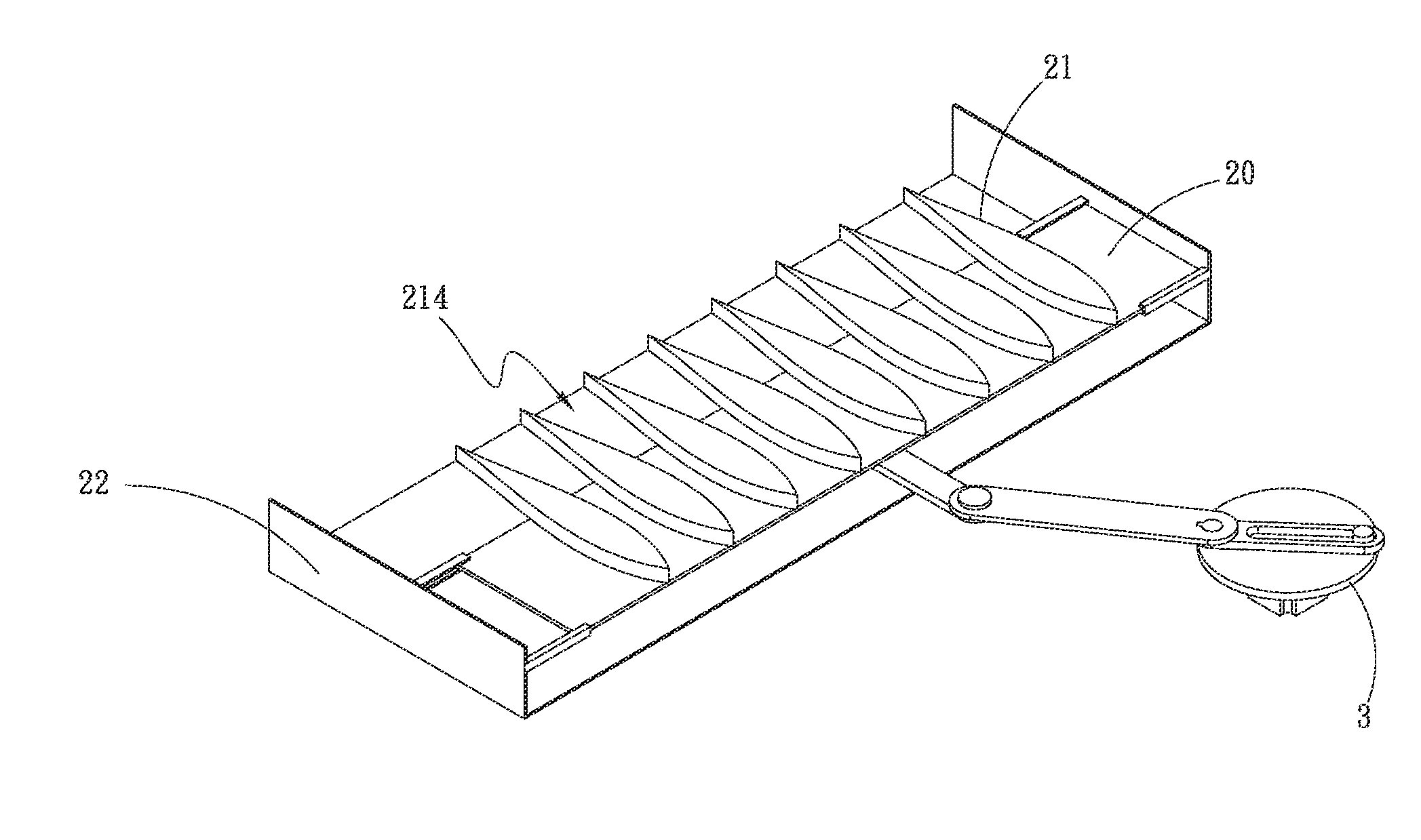
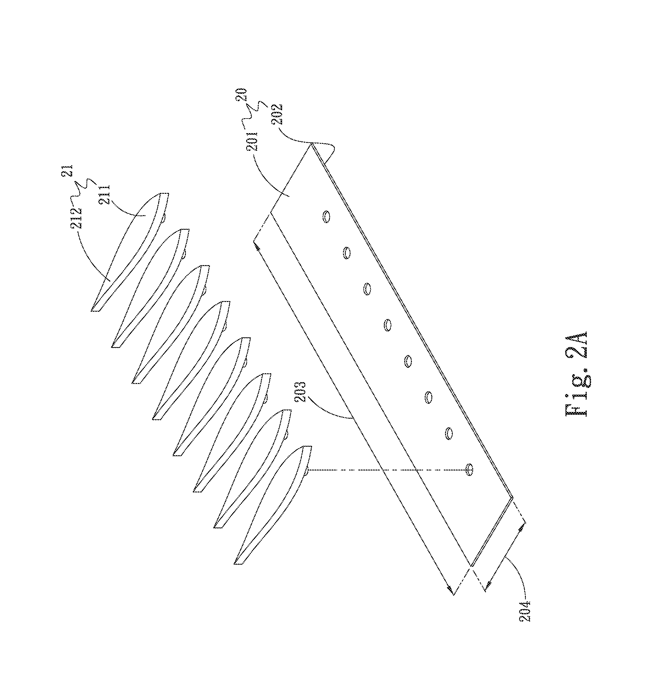
[0027]Please refer to FIGS. 2A and 2B. FIG. 2A is a perspective exploded view of a first embodiment of the swing fan structure of the present invention. FIG. 2B is a perspective assembled view of the first embodiment of the swing fan structure of the present invention. According to the first embodiment, the swing fan structure of the present invention includes a main body 20 and multiple blades 21. The main body 20 has an upper face 201 and a lower face 202 opposite to the upper face 201. The main body 20 also has a long side 203 and a short side 204. The blades 21 are disposed on the upper face 201 of the main body 20 in parallel to each other. The blades 21 define therebetween a flow way 214. The blades 21 are drivable by the main body 20 to reciprocally move along the long side 203.
[0028]Please refer to FIGS. 3A and 3B. FIG. 3A is a perspective exploded view of the first embodiment of the swing fan structure of the present invention. FIG. 3B is a perspective assembled view of the...
PUM
 Abstract
Description
Claims
Application Information