Multi-stage flash evaporator

a technology of flash evaporator and evaporator body, which is applied in the direction of distillation in boiler/still, separation process, chemistry apparatus and process, etc., can solve the problems of limited possibilities of increasing unit capacity of tube evaporators of the prior art, and achieve the effect of minimizing the overall dimensions, foot print, volume and weight, and minimizing the labor cost of manufacturing and space in the plant layou

Inactive Publication Date: 2012-10-18
ALT FRIEDRICH
View PDF10 Cites 5 Cited by
  • Summary
  • Abstract
  • Description
  • Claims
  • Application Information

AI Technical Summary

Benefits of technology

[0012]The main concept of the present invention is a multi stage flash cross tube evaporator, comprising a plurality of at least two vertically stacked tiers, wherein each tier comprises a plurality of flash stages including a first flash stage, a last flash stage and a plurality of intermediate flash stages, and wherein the flash stages within each individual tier are configured to operate in a serial flow communication and in parallel to th

Problems solved by technology

The cross tube evaporators of the prior art have technically limited possibilities to increase the unit capacities beyond the ma

Method used


Image

  • Multi-stage flash evaporator
  • Multi-stage flash evaporator
  • Multi-stage flash evaporator

Examples


Embodiment Construction

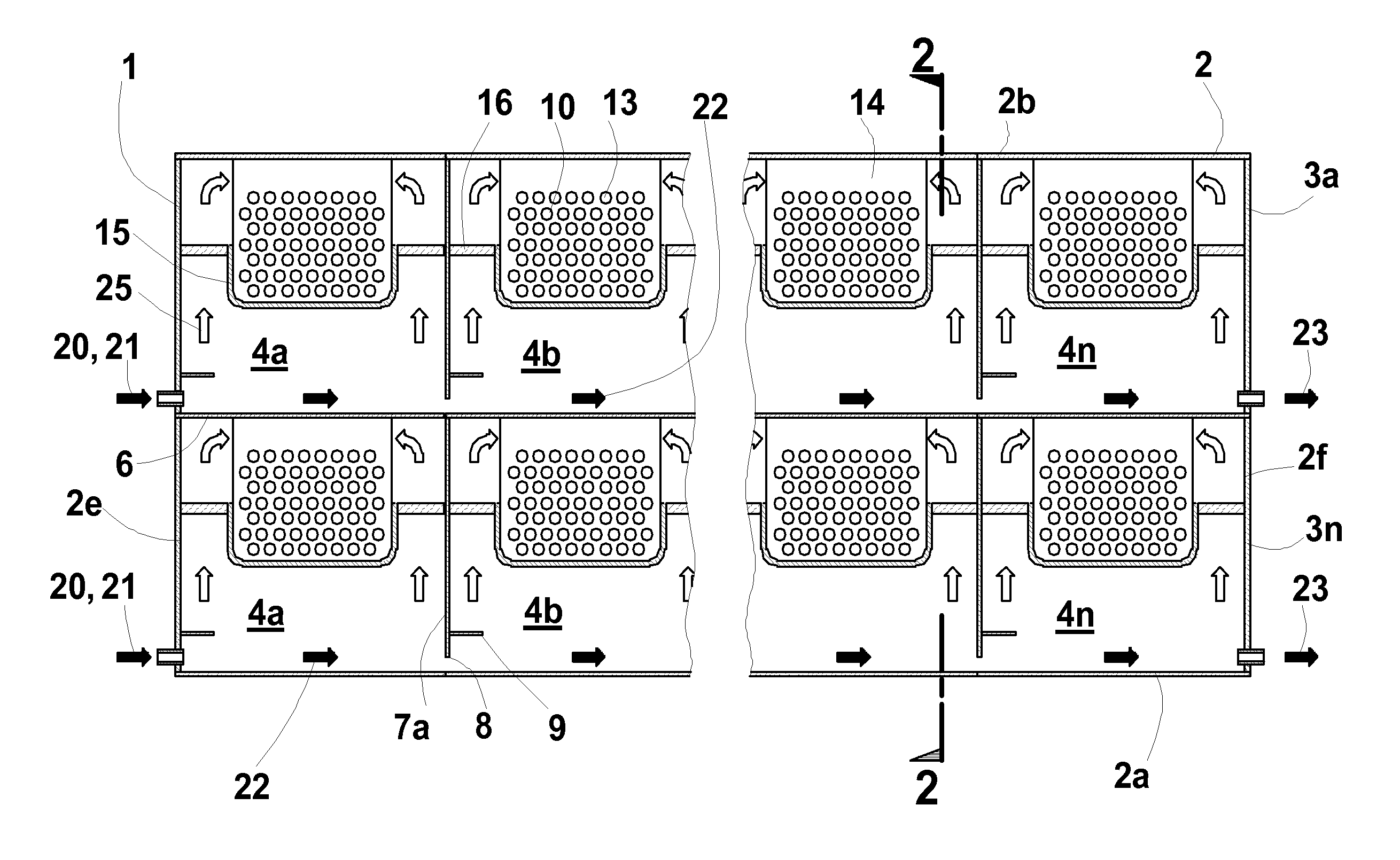
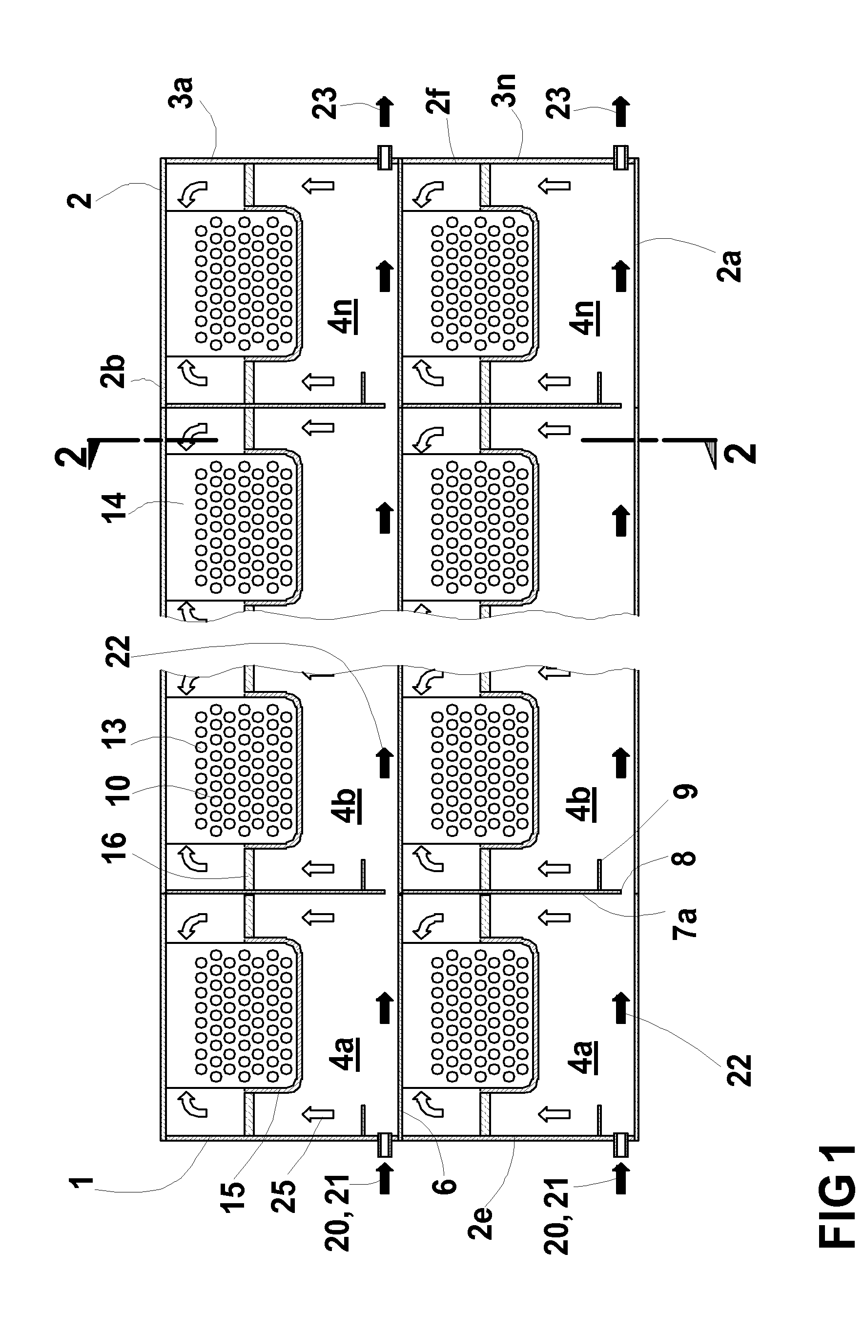
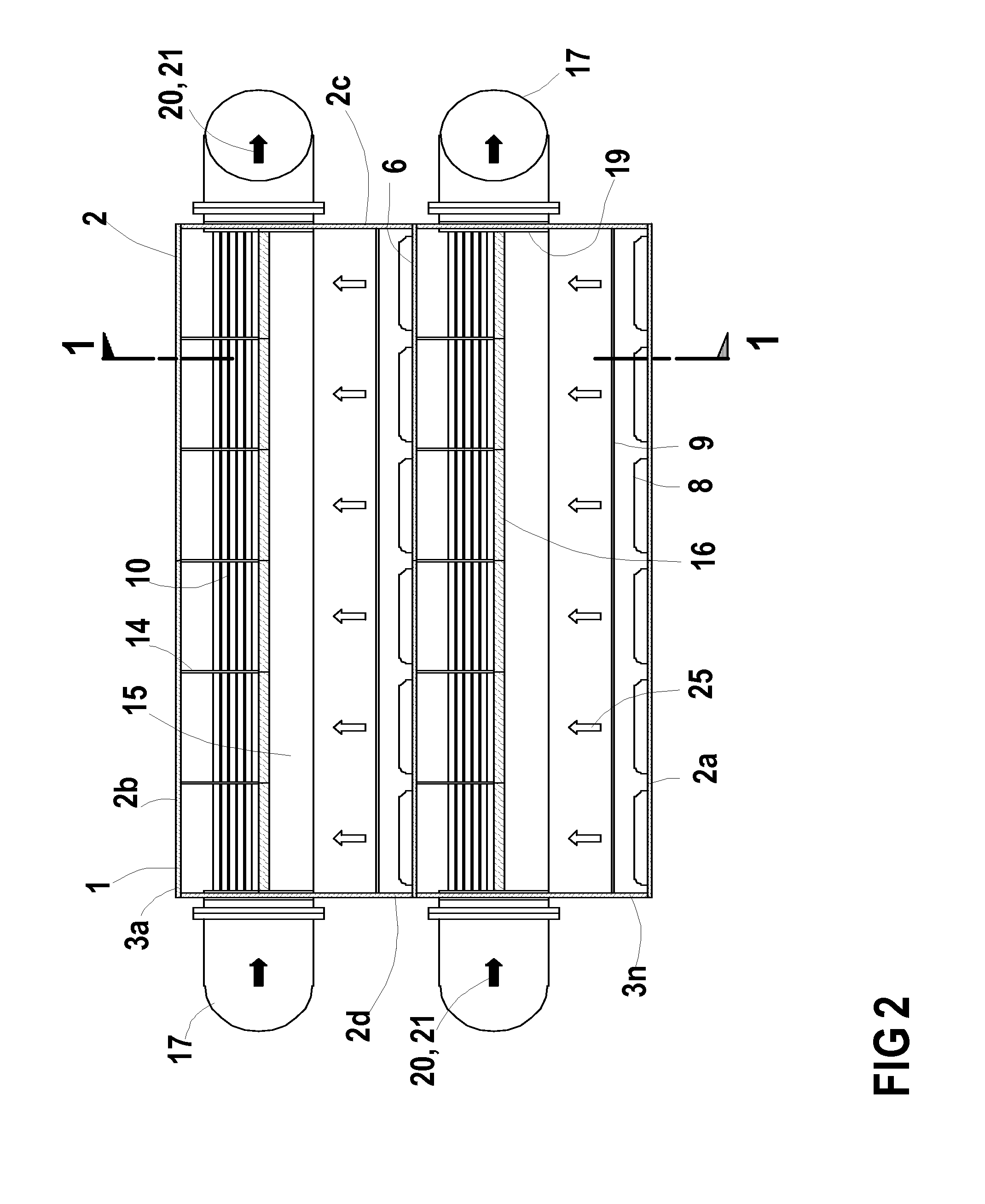
[0032]Examples of a multi stage flash cross tube evaporator 1 of the present invention are shown in FIG. 1 to FIG. 7, while examples of flow schematics for seawater desalination plants comprising an evaporator 1 of the present invention are shown in FIG. 8 to FIG. 11.

[0033]A first example of the multi stage flash cross tube evaporator of the present invention is shown in a longitudinal section FIG. 1 and a cross section FIG. 2. The evaporator 1 comprises an evaporator shell 2 with an evaporator shell bottom 2a, an evaporator shell roof 2b, a left side wall 2c, a right side wall 2d, a front wall 2e and an end wall 2f. The shell 2 is internally divided by at least one horizontal tier partition 6 into a plurality of at least two tiers, with at least a top tier 3a and a bottom tier 3n. Further intermediate tiers may be located in between the top tier 3a and the bottom tier 3n like the tier 3b shown in the schematic FIG. 10. The horizontal tier partition 6 is extending substantially in a...


PUM


Abstract

The present invention provides a configuration of a multi stage flash cross tube evaporator comprising a plurality of at least two tiers, wherein each tier comprises a first flash stage a plurality of intermediate flash stages and a last flash stage, wherein the flash stages in each tier are configured in a serial flow communication and the flash stages of each tier are configured to be in parallel flow communication to the flash stages in the other tier(s). Such configuration allows to reduce the size of the tube bundles, flash stages and evaporator shell compared to multi stage flash cross tube evaporators of prior art. With the resulting reduced evaporator weight and reduced foot print the cost of an evaporator and other related cost can be reduced.

Description

CROSS-REFERENCE TO RELATED APPLICATIONS[0001]Not Applicable.STATEMENT REGARDING FEDERALLY SPONSORED RESEARCH OR DEVELOPMENT[0002]Not Applicable.REFERENCE TO A SEQUENCE LISTING[0003]Not Applicable.BACKGROUND OF THE INVENTION[0004]A multi-stage flash evaporator is the main component of a seawater desalination plant for producing distilled water from seawater. Most evaporators for large capacity desalination plants are currently of a ‘cross tube’ type with all flash stages arranged in a single tier configuration, being build with evaporator unit capacities up to about 25 million gallons per day or about 100,000 cubic meters per day of distillate production.[0005]A multi-stage flash evaporator comprises a plurality of flash stages, in existing plants typically between 15 and 30. While a heated solution, typically seawater or brine, enters the first flash stage at its highest temperature, the solution flashes down in each consecutive flash stage to a lower temperature compared to the tem...

Claims


Application Information

Patent Timeline
IPC IPC(8): B01D3/06
CPCB01D3/065
Inventor ALT, FRIEDRICH
Owner ALT FRIEDRICH
Why Eureka
Try Eureka