System and method for component maintenance

a technology for component maintenance and maintenance, applied in the field of system and method for component maintenance, to achieve the effect of reducing the likelihood of damage to components, simple, and constant flow out of the vessel

Inactive Publication Date: 2014-09-18
MOLTEN METAL EQUIP INNOVIATIONS LLC
View PDF5 Cites 64 Cited by
  • Summary
  • Abstract
  • Description
  • Claims
  • Application Information

AI Technical Summary

Benefits of technology

[0027]A key advantage of the present system is that the amount of molten metal entering the launder, and the level in the launder, can remain constant regardless of the amount of or level of molten metal entering the transfer chamber with prior art systems, the metal level in the transfer chamber rises and falls and can affect the molten metal level in the launder. Alternatively, the molten metal can be removed from the vessel utilizing a tap-out plug, which is associated with the problems previously described.
[0031]It has also been discovered that by making the launder either level (i.e., at a 0° incline) or inclined backwards towards the vessel so that molten metal in the launder drains back into the vessel, the dross or skin that forms on the surface of the molten metal in the launder is not pulled away with the molten metal entering downstream vessels. Thus, this dross is less likely to contaminate any finished product, which is a substantial benefit. Preferably, a launder according to the inventor is formed at a horizontal angle leaning back towards the vessel of 0° to 10°, or 0° to 5°, or 0° to 3°, or 1° to 3°, or at a slope of about ⅛″ for every 10′ of launder.
[0032]Also, a system according to the invention may include one or more degassers in a vessel (preferably a plurality of degassers) wherein each degasser is preferably in a separate compartment in communication with one or more other degasser compartments (if multiple degassers are used). The degassers degas the molten metal and the molten metal moves out of the system in a low-turbulence stream generated by a transfer pump system according to the invention, which helps to maintain a relatively constant flow out of the vessel.
[0033]Further, other aspects of the invention include a simple, time-saving method and system to remove components from a vessel to perform maintenance and to place them back into the vessel while reducing the likelihood of damaging the components.

Problems solved by technology

Alternatively, the molten metal can be removed from the vessel utilizing a tap-out plug, which is associated with the problems previously described.

Method used


Image

  • System and method for component maintenance
  • System and method for component maintenance
  • System and method for component maintenance

Examples


Embodiment Construction

[0067]Turning now to the drawings, where the purpose is to describe a preferred embodiment of the invention and not to limit same, systems and devices according to the invention will be described.

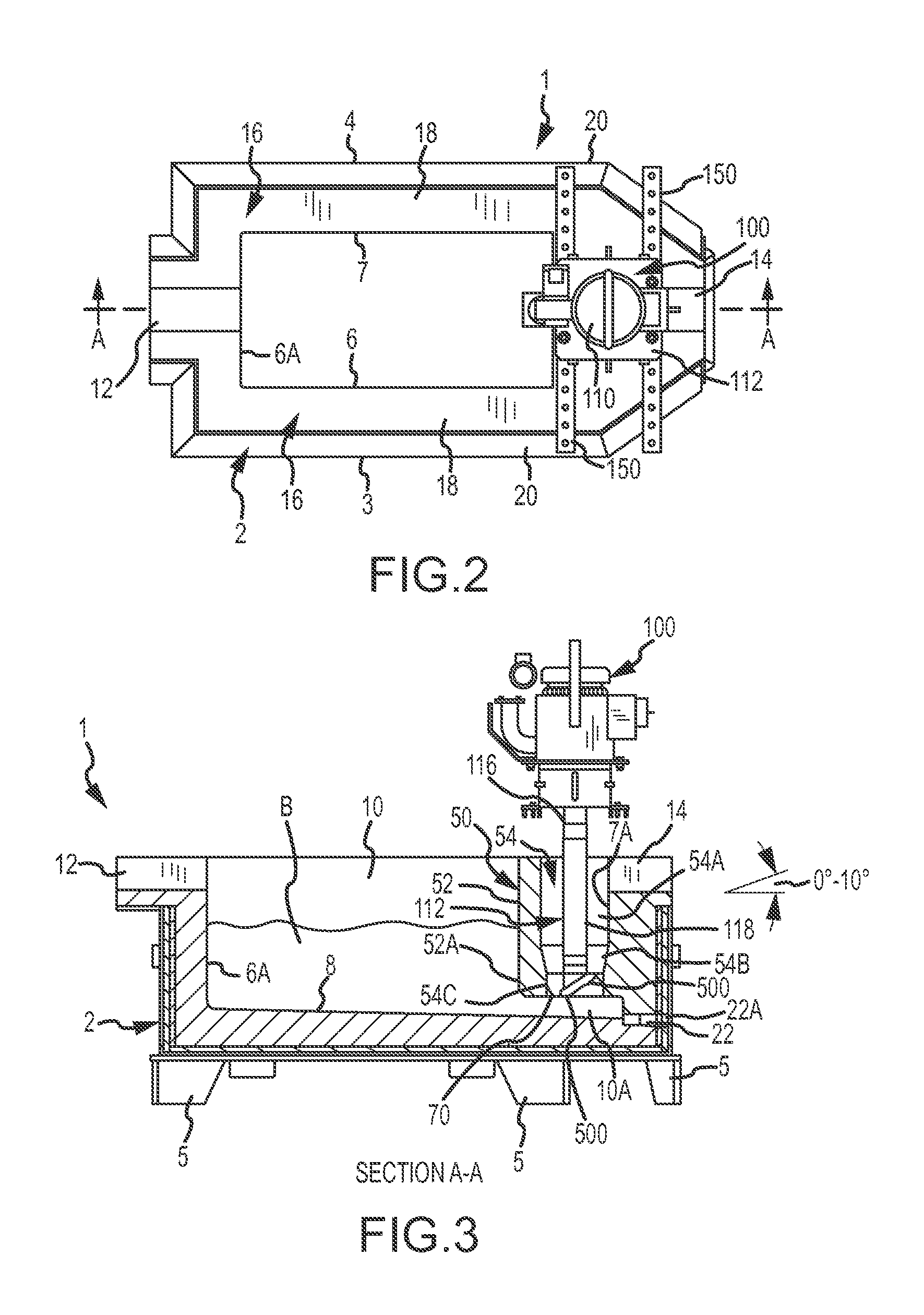
[0068]The invention includes a transfer chamber used with a vessel for the purpose of transferring molten metal out of the vessel in a controlled fashion using a pump, rather than relying upon gravity. It also is more preferred than using a transfer pump having a standard riser tube (such as the transfer pumps disclosed in the Background section) because, among other things, the use of such pumps create turbulence that creates dross and the riser tube can become plugged with solid metal.

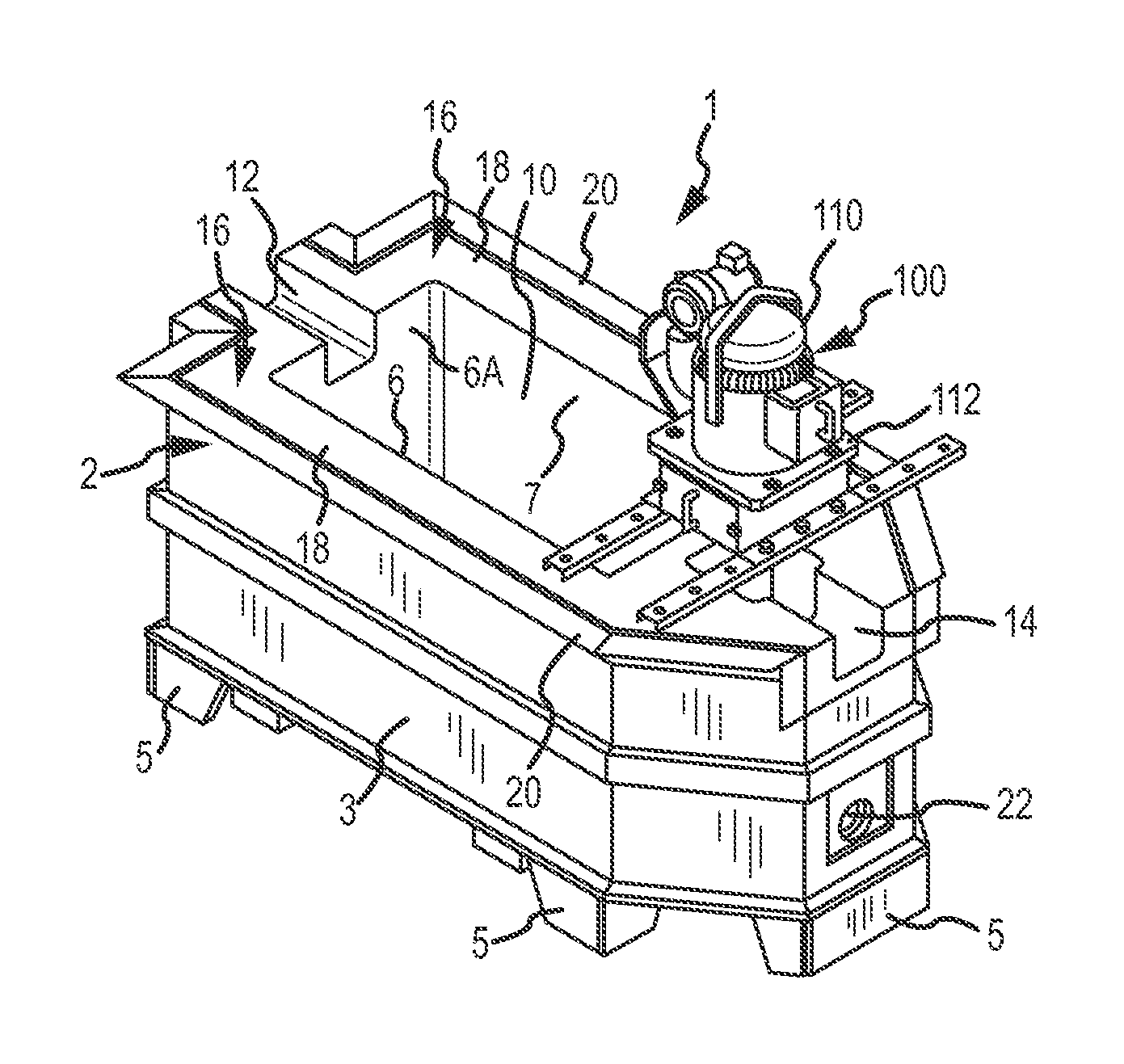
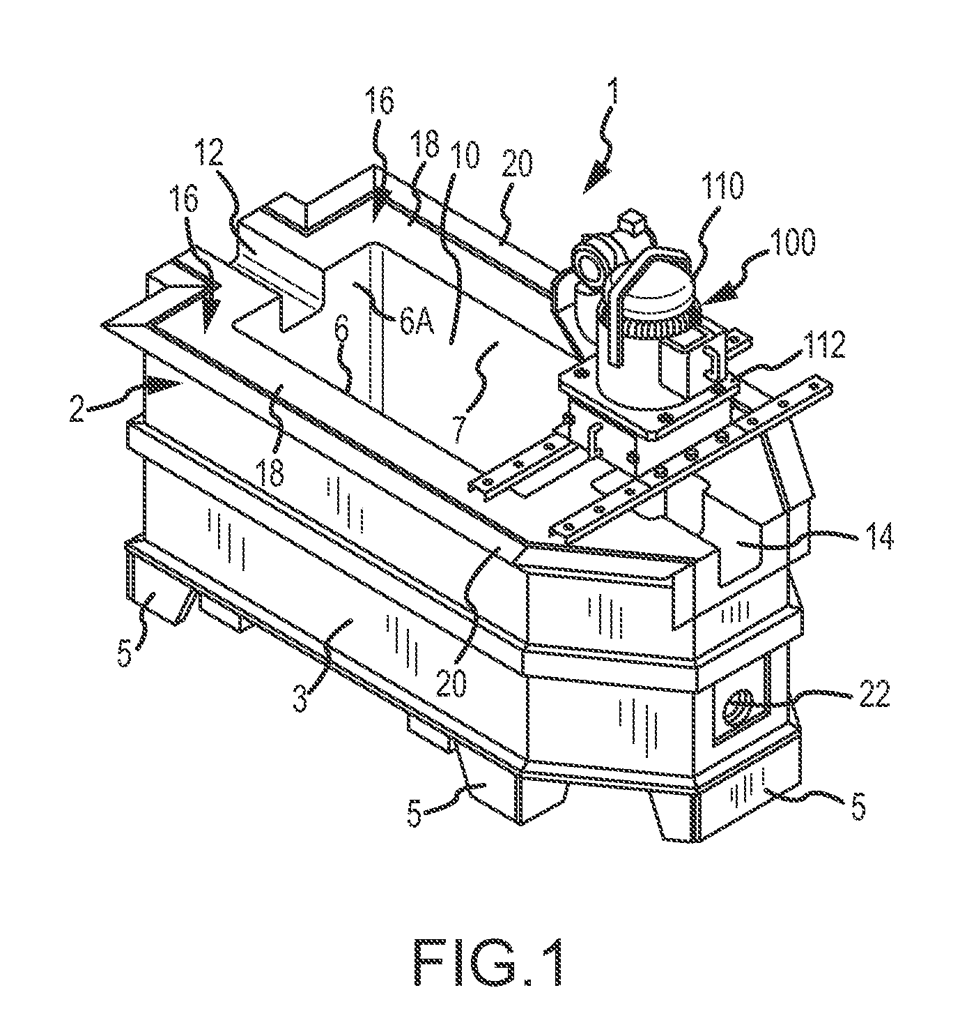
[0069]FIGS. 1-6 show one preferred embodiment of the invention. A system 1 comprises a vessel 2, a transfer chamber 50 and a pump 100. Vessel 2 can be any vessel that holds molten metal (depicted as molten metal bath B), and as shown in this embodiment is an intermediary holding vessel. Vessel 2 has a first ...


PUM

PropertyMeasurementUnit
lengthaaaaaaaaaa
lengthaaaaaaaaaa
lengthaaaaaaaaaa

Abstract

Aspects of the invention include a transfer chamber constructed inside of or next to a vessel used to retain and degas molten metal. The transfer chamber is in fluid communication with the vessel so molten metal from the vessel is pulled through the vessel by the pump as it is degassed. This helps maintain a generally constant flow of molten metal through the degassing vessel. Other aspects relate to a system and method for efficiently performing maintenance on components positioned in a vessel.

Description

CROSS-REFERENCE TO RELATED APPLICATIONS[0001]This application incorporates by reference the portions of U.S. patent application Ser. No. 13 / 797,616, filed on Mar. 12, 2013, by Paul V. Cooper, that are not inconsistent with this disclosure. This application also incorporates by reference the portions of U.S. patent application Ser. No. 08 / 489,962 (Now U.S. Pat. No. 5,678,807) filed Jun. 13, 1995, by Paul V. Cooper, U.S. patent application Ser. No. 12 / 853,255 filed Aug. 9, 2010, by Paul V. Cooper, U.S. patent application Ser. No. 12 / 878,984 filed Sep. 9, 2010, by Paul V. Cooper, U.S. patent application Ser. No. 12 / 880,027 filed Sep. 9, 2010, by Paul V. Cooper, U.S. patent application Ser. No. 13 / 106,853 filed May 12, 2011, by Paul V. Cooper, and U.S. patent application Ser. No. 13 / 725,383 filed Dec. 21, 2012, by Paul V. Cooper, that are not inconsistent with this disclosure.FIELD OF THE INVENTION[0002]The invention relates to a system for moving molten metal out of a vessel, and compo...

Claims


Application Information

Patent Timeline
Patent Type & Authority Applications(United States)
IPC IPC(8): F27D3/06C22B9/00C21C7/00
CPCC22B9/05C22B9/00C21C7/00F27D3/06C21C7/04F27D25/005F27D2003/166
Inventor COOPER, PAUL V.
Owner MOLTEN METAL EQUIP INNOVIATIONS LLC
Why Eureka
Try Eureka