
Disc coupling break monitoring device

a monitoring device and disc technology, applied in the field of disc couplings, can solve the problems of internal disc failure, disc failure of discs located on the outside of the pack, and disc failure of individual discs

Inactive Publication Date: 2014-09-18
LOVEJOY
View PDF3 Cites 3 Cited by
  • Summary
  • Abstract
  • Description
  • Claims
  • Application Information

AI Technical Summary

Benefits of technology

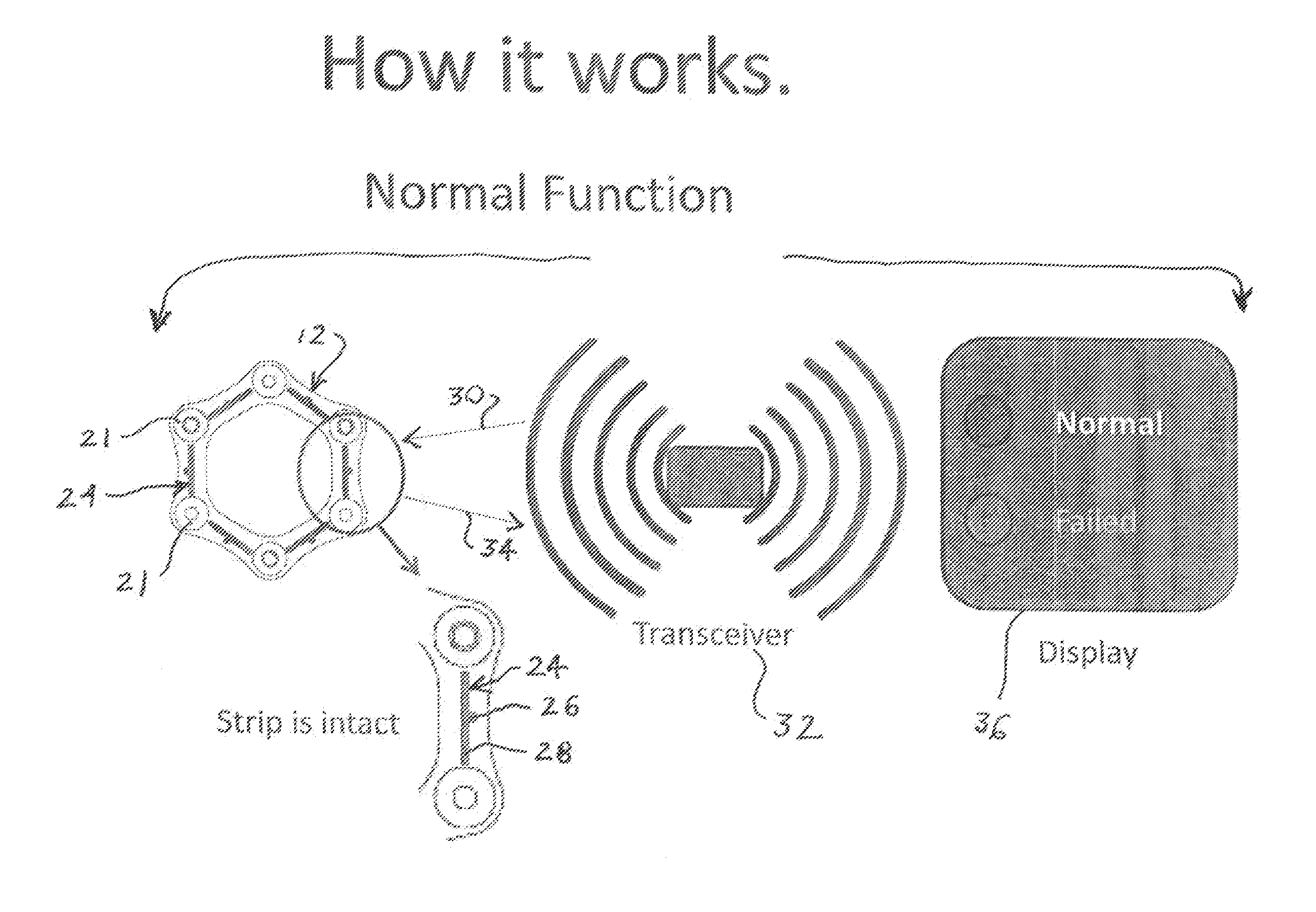
This patent describes a device that monitors when the disc pack in a disc coupling becomes worn out and may fail, alerting the operator of the equipment and allowing for timely replacement of the coupling. The device uses a radio frequency identification tag and an electrically conductive strip to establish a circuit around the outermost discs in the pack. When the outermost disc breaks, the circuit is broken and an alert is triggered. The device operates continuously with the machinery and does not require the removal of the safety shields or shutdown of the machine to examine the coupling. This invention helps prevent sudden failure of the coupling and downtime for maintenance.

Problems solved by technology

In operation, the portion of the coupling that is prone to failure is the individual discs.
Generally, the discs located on the outside of the pack fail before the internal discs fail.
The time to complete failure can be relatively short, and once the discs begin failing, the remaining discs need to absorb the additional load resulting in their rapid failure.
If the failure of the outermost discs is not discovered early in the disc pack failure, the entire disc pack will eventually fail resulting in a system failure and shutdown.
This was done with the machine running, which presents a safety hazard as the machine should not be run with the coupling guards removed.
Another disadvantage is that this type of inspection required a trained maintenance person to physically do the inspection.
This method did not allow for continuous monitoring of the disc pack as the inspection only disclosed the condition of the disc at the moment in time that it is inspected.
The disc may be ready to fail in the next few minutes or hours, and the maintenance person has no way of knowing the condition of the disc until the entire coupling failed.
This method is expensive as it requires a knowledgeable machine operator to disassemble the coupling, inspect the coupling and then reassemble the coupling.
Furthermore this method results in expensive downtime while the machine is not operational.

Method used


Image

  • Disc coupling break monitoring device
  • Disc coupling break monitoring device
  • Disc coupling break monitoring device

Examples


Embodiment Construction

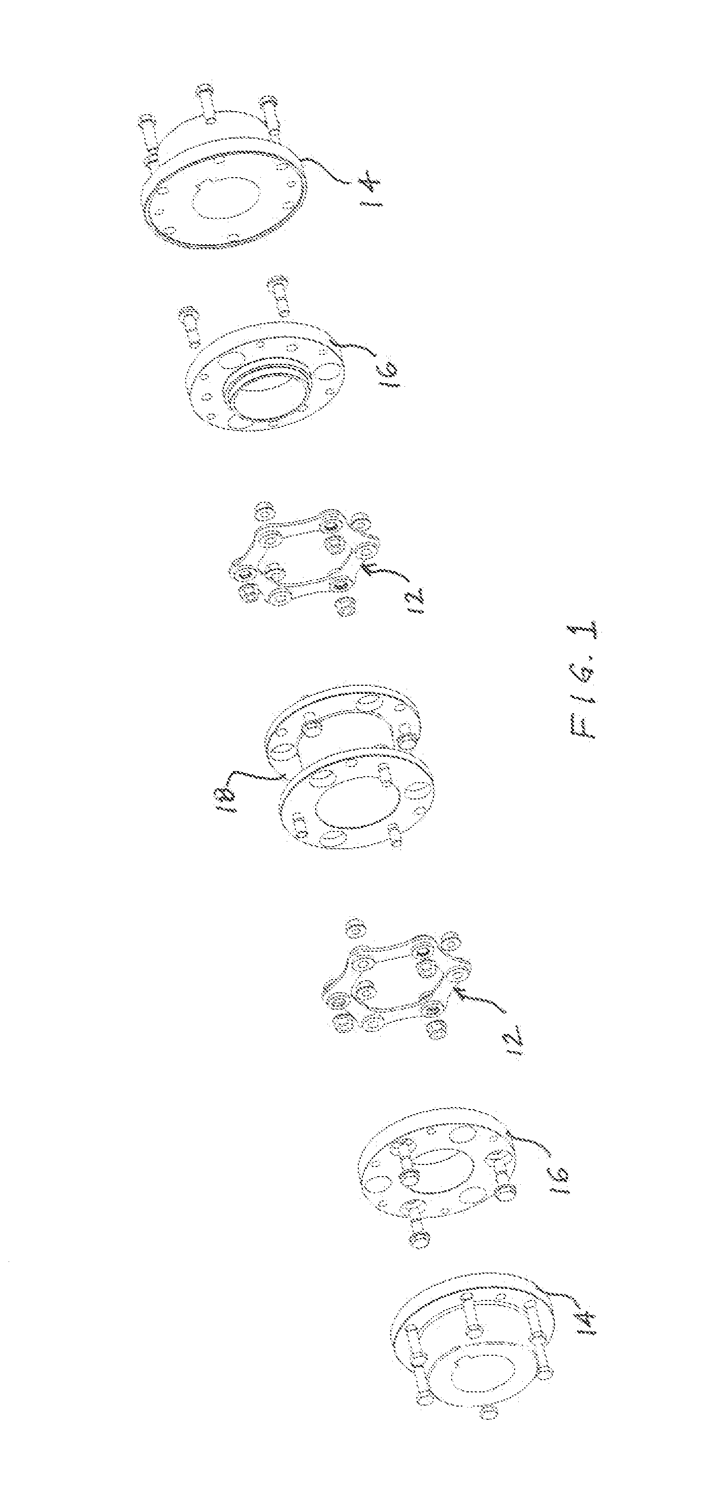
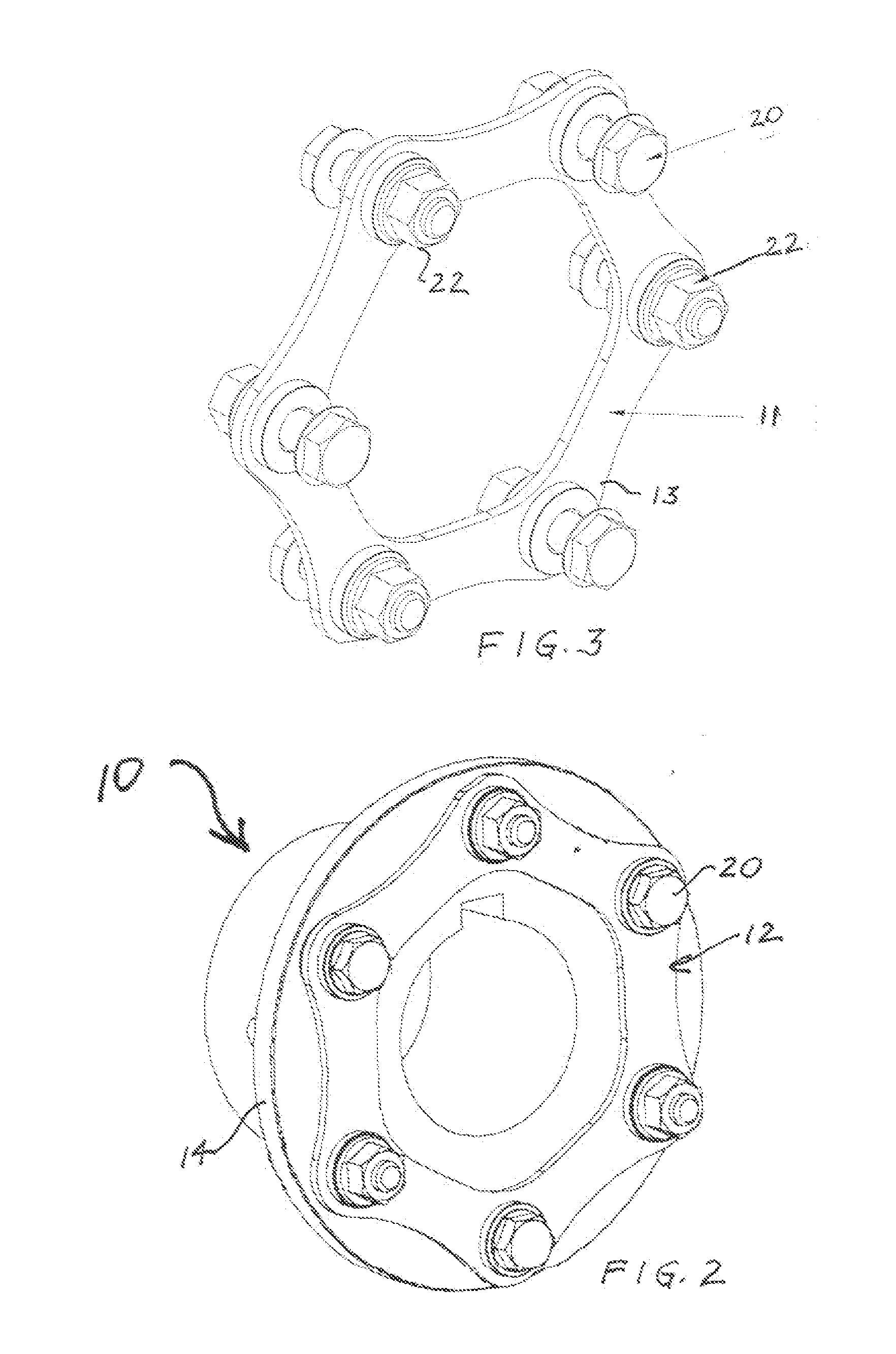
[0020]FIG. 1 illustrates and describes the basic disc coupling 10. There are a series of discs 11 that comprise the disc pack 12. The disc pack 12 is mounted between a pair of hubs 14. Depending on the particular application, the configuration of the disc coupling varies, but the common feature is that the hubs 14 are separated by and coupled to each other by means of the discs 12. In the coupling illustrated in FIG. 1, which is a coupling sold by Lovejoy, Inc. of Downers Grove, Ill., the illustrated coupling is an Industrial DI Type Coupling. There are two guard rings or anti-flail flanges 16, each one mounted two one of the hubs 14. There is a disc pack 12 mounted between a spacer 18 and the anti-flail flange. In the alternate embodiment of FIG. 2, the disc pack 12 is mounted directly to and between two hubs 14 and no spacer or anti-flail flanges are used. In either instance, and throughout this application, there is a reference to an outermost disc 13, which is the exterior disc ...


PUM


Abstract

A break monitoring device for use with a disc coupling having an outermost disc disposed on a disc pack. There is an RFID tag mounted on the outermost disc which transmits a signal to a receiver or monitor. The RFID may be an active or passive tag. When the RFID tag is broken due to the outermost disc failing, the signal sent to the receiver is different than the signal sent during normal operation. This triggers an alert that the outermost disc has failed and the machine can be shut down in an orderly manner.

Description

BACKGROUND AND SUMMARY OF INVENTION[0001]This invention relates to disc couplings and more particularly to a device for monitoring when the disc pack begins to fail prior to a system failure.[0002]Disc couplings are widely used in industrial applications to couple two shafts for the transmission of power from a driving source to a driven piece of machinery. Examples of disc couplings are found in disc couplings manufactured and sold by Lovejoy, Inc. located in Downers Grove Ill. Examples of disc couplings can be found in the Lovejoy, Inc. catalog under the section entitled “Disc Couplings” and are fully illustrated in the catalog. Generally the disc coupling uses two or more hubs and one or more disc packs mounted between the hubs. The disc packs are formed from multiple individual discs. In operation, the portion of the coupling that is prone to failure is the individual discs. Generally, the discs located on the outside of the pack fail before the internal discs fail. Once the dis...

Claims


Application Information

Patent Timeline
Patent Type & Authority Applications(United States)
IPC IPC(8): G06K7/10G08B23/00
CPCG08B23/00G06K7/10366F16D3/78F16D9/00F16D2300/18
Inventor HENNESSY, MIKEFAGAN, DANIEL R.KREJCI, JAMES
Owner LOVEJOY
Learn More