Image recording apparatus

a technology of image recording and recording device, which is applied in the direction of printing, other printing apparatus, etc., can solve the problems of loss of heat of light source transported to the portion to be connected, difficulty in improving the cooling efficiency of light source, etc., and achieve efficient cooling of light source, efficient radiation of light source heat, and reduced pressure loss of air current due to cooling fan

Active Publication Date: 2014-09-18
SEIKO EPSON CORP
View PDF2 Cites 0 Cited by
  • Summary
  • Abstract
  • Description
  • Claims
  • Application Information

AI Technical Summary

Benefits of technology

[0016]In the image recording apparatus, the heat pipe may include a first region which extends in parallel to a main surface of the light source substrate, a second region which extends in a direction which is further separated from the light source substrate than the first region by extending in a direction which crosses the main surface of the light source substrate by being bent from the first region, in which the portion to be connected is provided in the first region, and the portion to be cooled is provided in the second region. In such a configuration, it is possible to radiate heat of the light source which is transported to the portion to be cooled using the cooling fan which faces the portion to be cooled which is provided in the second region of the heat pipe, by connecting the first region of the heat pipe to the light source substrate, and on the other hand, by drawing the second region of the heat pipe from the light source substrate. For this reason, it is possible for the cooling fan to cool down the portion to be cooled using air which is relatively cooler than air in the vicinity of the light source, and to efficiently radiate the heat of the light source which is transported to the portion to be cooled. As a result, it is possible to efficiently cool down the light source of the light irradiator.
[0017]In the image recording apparatus, at least a part of the portions to be cooled may be arranged at a position which is farther from the recording medium than an end portion of the ejecting head on a side which is opposite to a recording medium side. Accordingly, in such a configuration, it is not necessary to extend the ventilation member from the air inlet or the air outlet to the light source, and it is possible to make the ventilation member short, compared to a case in which the ventilation member is extended from the air inlet or the air outlet to the light source. Since it is possible to make the ventilation member short in this manner, a pressure loss of an air current due to the cooling fan can be reduced. Accordingly, cooling efficiency is increased compared to a case in which a long ventilation member is used, when the same cooling fan is used.

Problems solved by technology

However, there has been a case in which, when the fan is set to be close to the light source, warm air in the vicinity of the light source is sent to the light source by the fan, and as a result, it is difficult to improve cooling efficiency of the light source.
In addition, the heat of the light source which is transported to the portion to be connected is lost due to the cooling fan.

Method used


Image

  • Image recording apparatus
  • Image recording apparatus
  • Image recording apparatus

Examples


Embodiment Construction

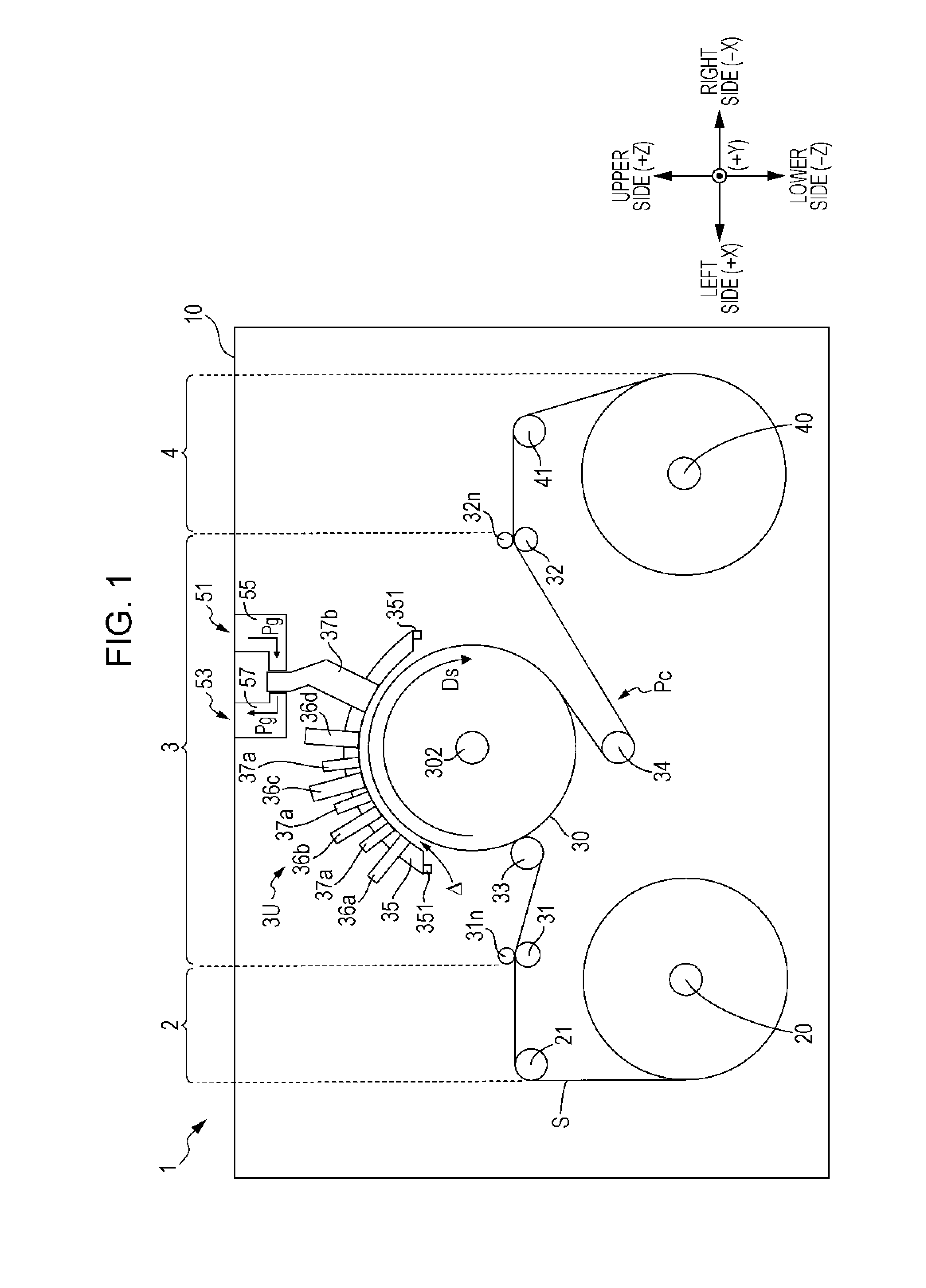
[0022]FIG. 1 is a front view which schematically illustrates a configuration of a printing device to which the present invention can be applied. In addition, an XYZ orthogonal coordinate system corresponding to the horizontal direction X, the forward and backward direction Y, and the vertical direction Z of a printing device 1 is displayed in order to make an arrangement relationship in each unit of the device clear in FIG. 1.

[0023]In a printing device 1, a feeding unit 2, a processor 3, and a winding unit 4 are arranged in the horizontal direction X, and each of the functional units 2, 3, and 4 are accommodated in a housing member 10. The feeding unit 2 and the winding unit 4 include a feeding axis 20 and a winding axis 40, respectively. In addition, both ends of a sheet S (web) are wound around a roll shape in the feeding axis 20 and the winding axis 40, and are stretched between the axes. The sheet S is transported to the processor 3 from the feeding axis 20 along a path Pc which...


PUM


Abstract

An image recording apparatus includes an ejecting head which ejects photocurable liquid onto the recording medium; and a light irradiator which radiates the light to the liquid which is ejected onto the recording medium, in which the light irradiator includes a light source substrate which is arranged so as to face the recording medium, and includes a light source which radiates the light to the recording medium; a heat transport member which includes a portion to be connected which is in thermal contact with the light source substrate, and a portion to be cooled which is located at a position which is further separated from the light source substrate than the portion to be connected, and transports heat from the portion to be connected to the portion to be cooled; and a cooling fan which cools down the portion to be cooled.

Description

BACKGROUND[0001]1. Technical Field[0002]The present invention relates to a technology in which a light source of a light irradiator emitting light which cures photocurable liquid from the light source is cooled down in an image recording apparatus which records an image on a recording medium using ejecting heads which eject the liquid.[0003]2. Related Art[0004]In JP-A-2010-000735, a printer which includes printer heads ejecting ultraviolet (UV) ink which is cured by being irradiated with UV rays, and a light source unit which radiates UV rays to UV ink which is landed on a printing medium is disclosed. The light source unit cures the UV ink by radiating the UV rays to the printing medium by emitting the UV rays from a light source facing the printing medium. In addition, the light source unit includes a fan which is arranged so as to face the light source, and suppresses a temperature rise in the light source by cooling down the light source using wind which is generated by the fan....

Claims


Application Information

Patent Timeline
Patent Type & Authority Applications(United States)
IPC IPC(8): B41J11/00B41J29/377
CPCB41J29/377B41J11/002B41J11/00214B41J11/00216
Inventor SHIIYA, TOMOYUKI
Owner SEIKO EPSON CORP
Why Eureka
Try Eureka