Three-dimensional coordinate scanner and method of operation

a three-dimensional coordinate and scanner technology, applied in the field of three-dimensional coordinate scanners, can solve the problems of missing or faulty point cloud data, operator may be unaware of or unable to eliminate a problem, and acquisition of high-accuracy point cloud data

Active Publication Date: 2014-09-18
FARO TECH INC
View PDF2 Cites 106 Cited by
  • Summary
  • Abstract
  • Description
  • Claims
  • Application Information

AI Technical Summary

Problems solved by technology

A number of issues may interfere with the acquisition of high accuracy point cloud data when using a laser scanner.
In some cases,

Method used


Image

  • Three-dimensional coordinate scanner and method of operation
  • Three-dimensional coordinate scanner and method of operation
  • Three-dimensional coordinate scanner and method of operation

Examples


Embodiment Construction

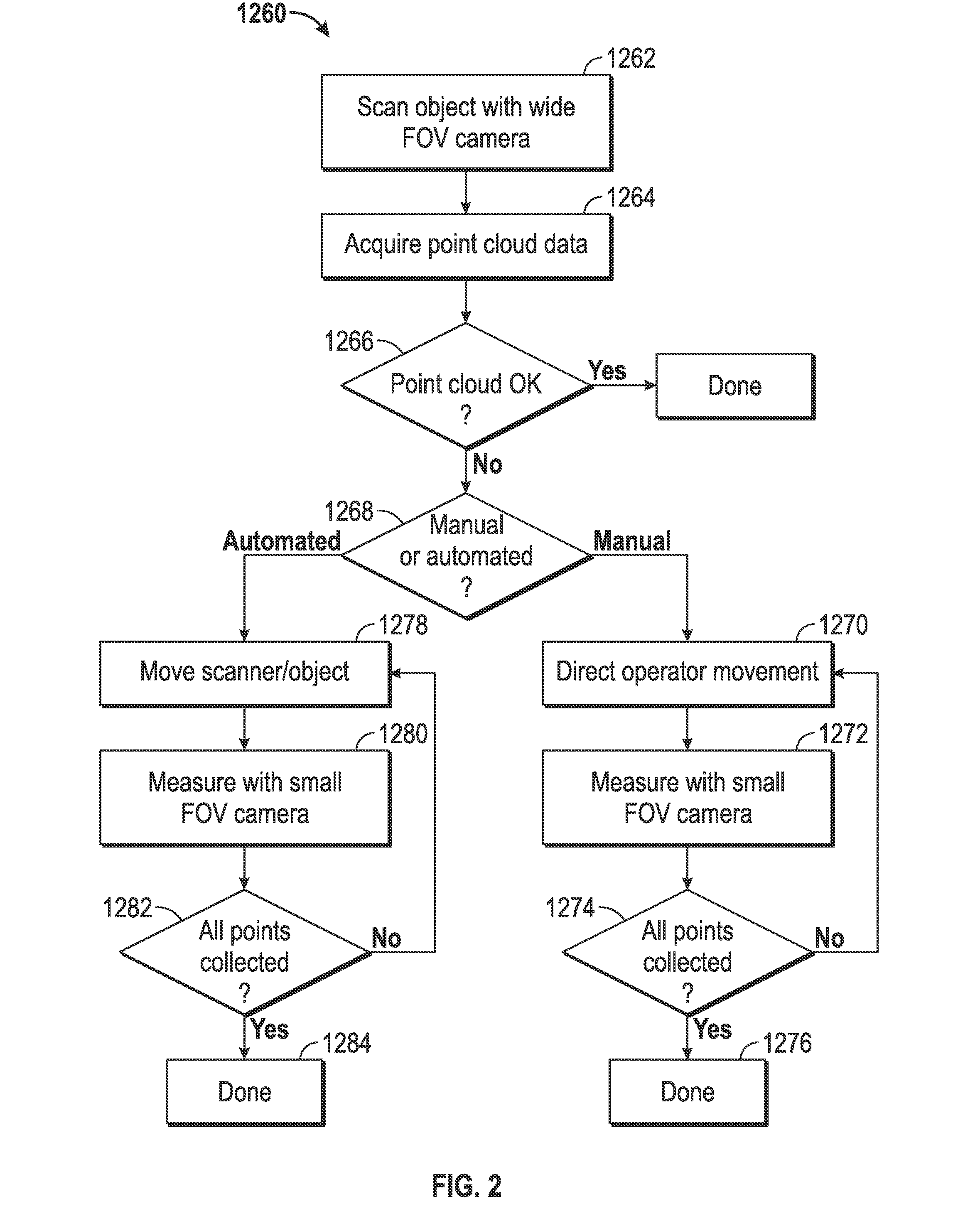
[0024]Embodiments of the present invention provide advantages increasing the reliability and accuracy of three-dimensional coordinates of a data point cloud acquired by a scanner. Embodiments of the invention provide advantages in detecting anomalies in acquired data and automatically adjusting the operation of the scanner to acquire the desired results. Embodiments of the invention provide advantages in detecting anomalies in the acquired data and providing indication to the operator of areas where additional data acquisition is needed. Still further embodiments of the invention provide advantages in detecting anomalies in the acquired data and providing indication to the operator where additional data acquisition may be acquired with a remote probe.

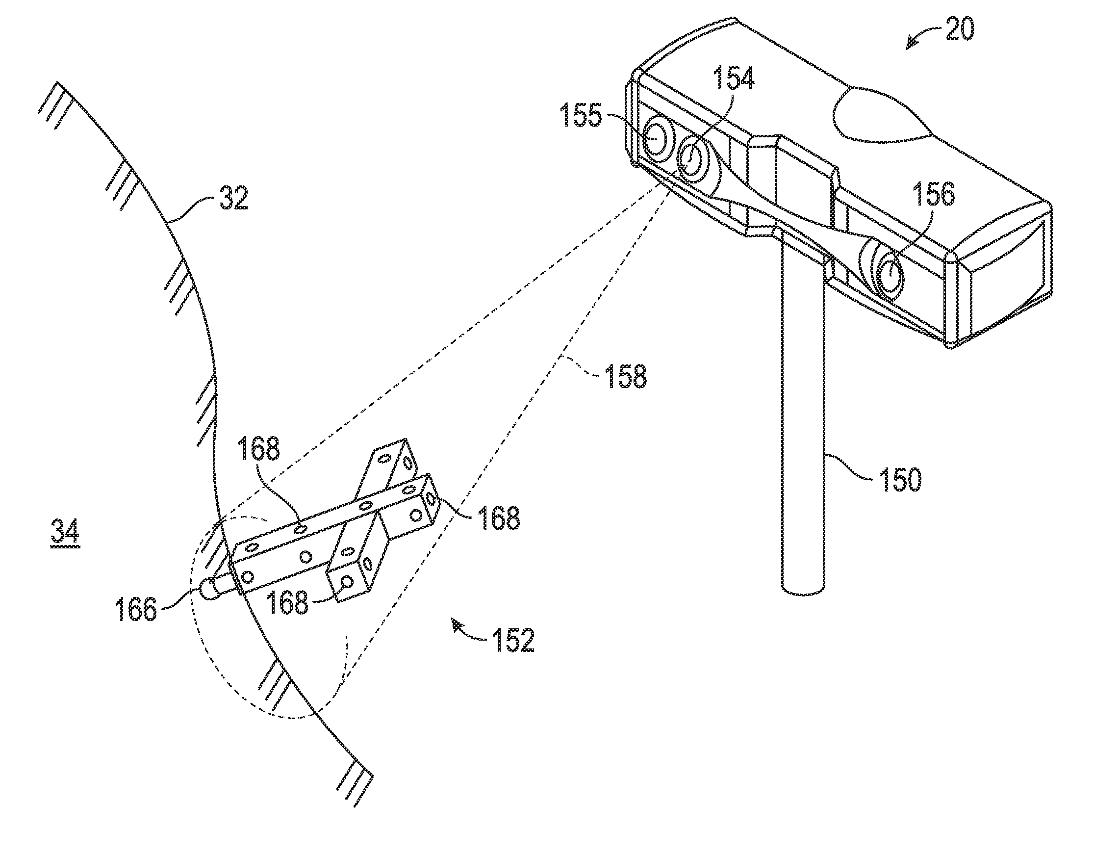
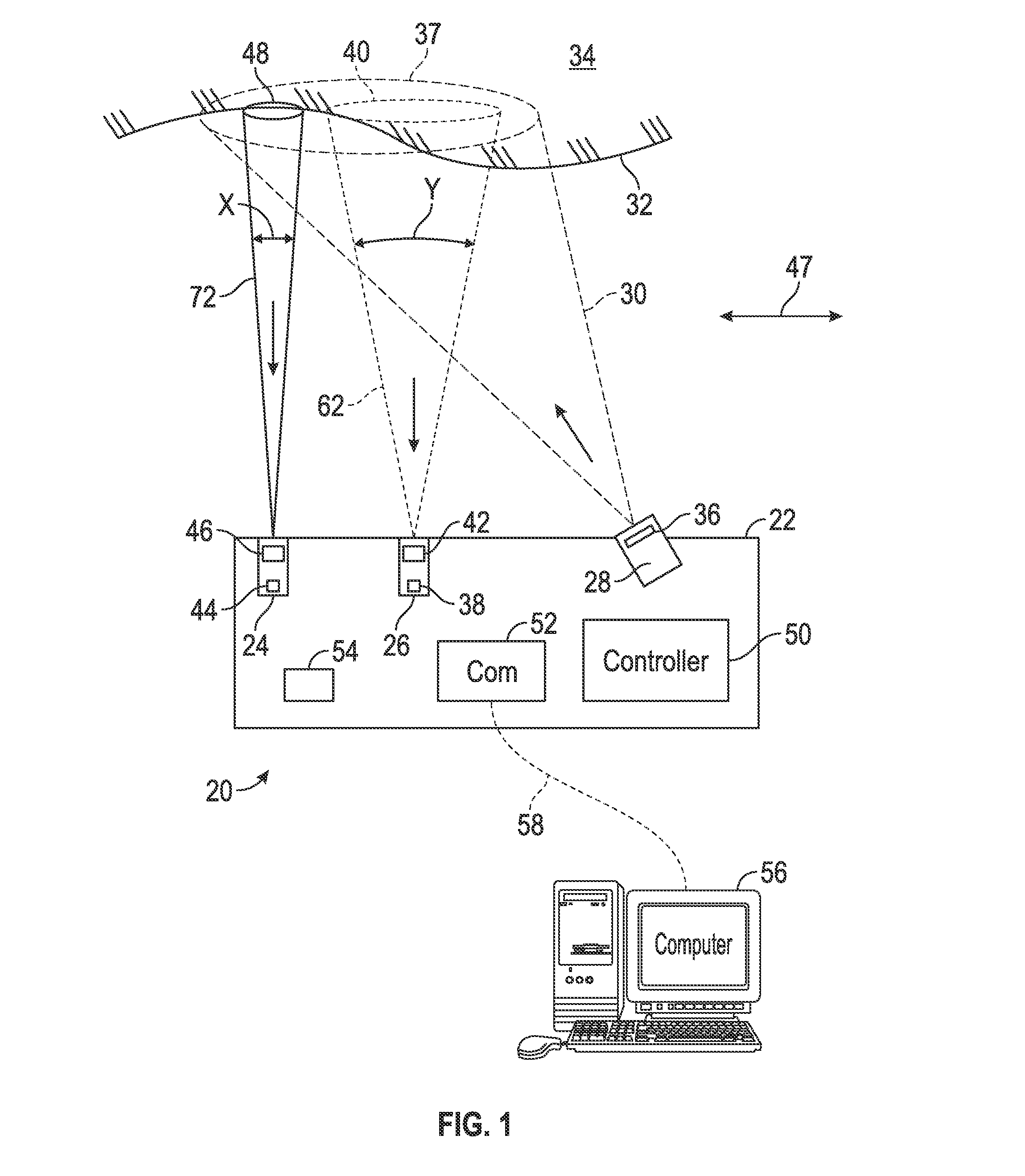
[0025]Scanner devices acquire three-dimensional coordinate data of objects. In one embodiment, a scanner 20 shown in FIG. 1 has a housing 22 that includes a first camera 24, a second camera 26 and a projector 28. The projector 28 emits ...


PUM


Abstract

A noncontact optical three-dimensional measuring device that includes a projector, a first camera, and a second camera; a processor electrically coupled to the projector, the first camera and the second camera; and computer readable media which, when executed by the processor, causes the first digital signal to be collected at a first time and the second digital signal to be collected at a second time different than the first time and determines three-dimensional coordinates of a first point on the surface based at least in part on the first digital signal and the first distance and determines three-dimensional coordinates of a second point on the surface based at least in part on the second digital signal and the second distance.

Description

BACKGROUND OF THE INVENTION[0001]The subject matter disclosed herein relates to a three-dimensional coordinate scanner and in particular to a triangulation-type scanner having multiple modalities of data acquisition.[0002]The acquisition of three-dimensional coordinates of an object or an environment is known. Various techniques may be used, such as time-of-flight or triangulation methods for example. A time-of-flight systems such as a laser tracker, total station, or time-of-flight scanner may direct a beam of light such as a laser beam toward a retroreflector target or a spot on the surface of the object. An absolute distance meter is used to determine the distance to the target or spot based on length of time it takes the light to travel to the target or spot and return. By moving the laser beam or the target over the surface of the object, the coordinates of the object may be ascertained. Time-of-flight systems have advantages in having relatively high accuracy, but in some case...

Claims


Application Information

Patent Timeline
IPC IPC(8): G01C3/10H04N13/239
CPCG01B11/002H04N13/0275H04N13/0203H04N13/0253G01B11/2531G01B21/045G01B11/2513G01S17/66G01B5/004G01C3/10G01S17/003G01S17/48H04N13/239G06T7/70G06T7/593H04N13/204H04N13/254H04N13/275G01B11/00G01B11/24G01B11/25G06T2200/04G06T2207/10028
Inventor TOHME, YAZIDPFEFFER, CHARLESBRIDGES, ROBERT E.
Owner FARO TECH INC
Why Eureka
Try Eureka