Camera Calibration System and Three-Dimensional Measuring System

a three-dimensional measuring and camera technology, applied in the field of three-dimensional measuring systems and cameras, can solve the problem that it is substantially impossible to automatically determine to which of the plurality of markers being imaged, and achieve the effect of reducing the number of markers

Inactive Publication Date: 2008-03-27
SPACEVISION
View PDF5 Cites 71 Cited by
  • Summary
  • Abstract
  • Description
  • Claims
  • Application Information

AI Technical Summary

Problems solved by technology

Because of this, when any of the markers on the upper surface of the head cannot be imaged by the stereoscopic camera because of, for example, a shadow of the object moving over the marker, it becomes substantially impossible to automatically determine to which of the plurality of markers the marker being imaged corresponds.

Method used


Image

  • Camera Calibration System and Three-Dimensional Measuring System
  • Camera Calibration System and Three-Dimensional Measuring System
  • Camera Calibration System and Three-Dimensional Measuring System

Examples


Embodiment Construction

[0024] A preferred embodiment of the present invention will now be described by reference to the drawings.

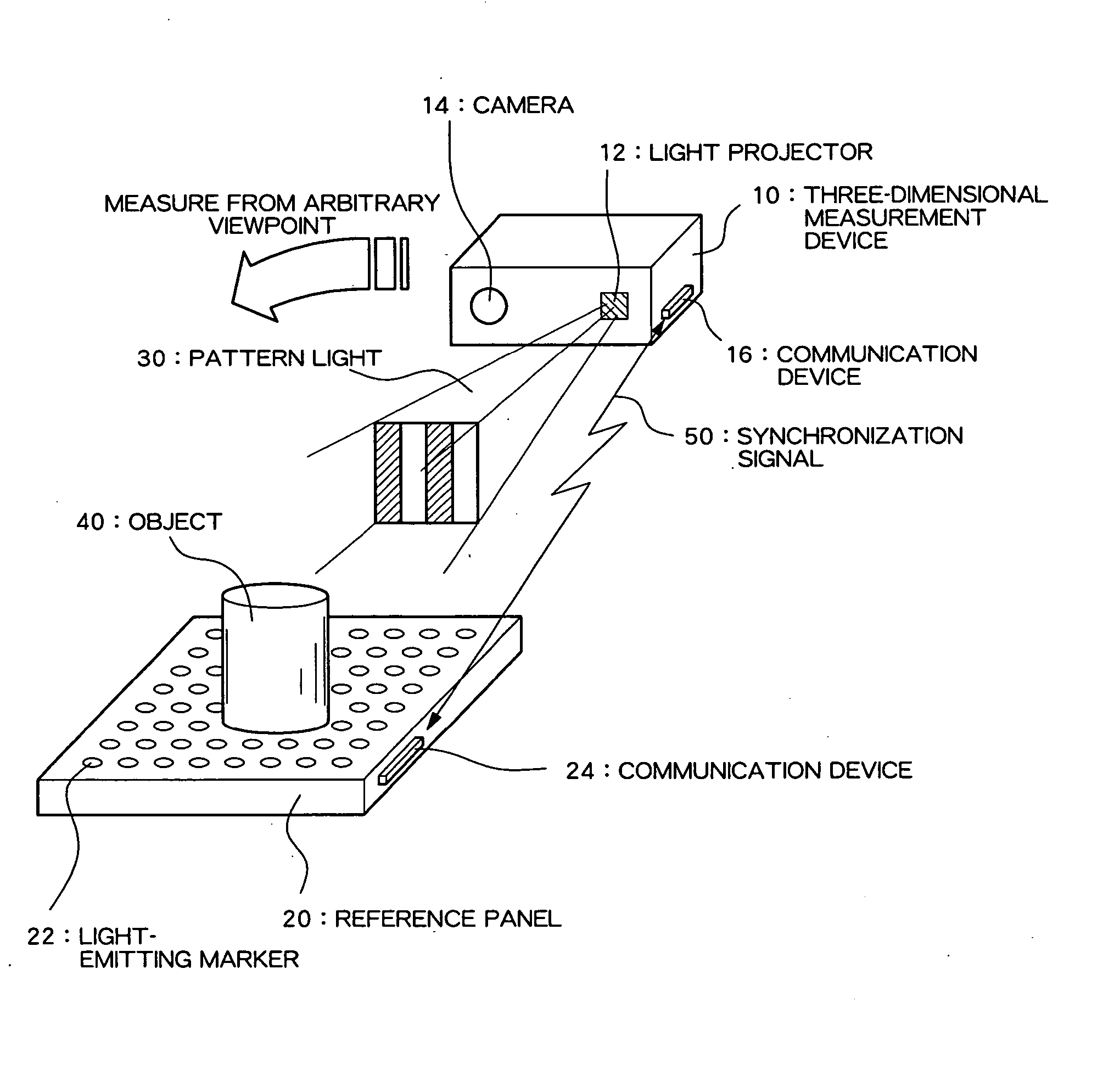
[0025]FIG. 1 is a diagram diagrammatically showing a structure of a three-dimensional measurement system according to a preferred embodiment of the present invention.

[0026] As shown in FIG. 1, the present system comprises a three-dimensional measurement device 10 and a reference panel 20. The three-dimensional measurement device 10 is a device which measures a three-dimensional shape through a spatial coding method, and comprises a light projector 12 which projects pattern light 30 for the spatial coding method, and a camera 14 which captures an image of an object and generates electronic captured image data. Although not shown, the three-dimensional measurement device 10 also comprises a storage device, a CPU (Central Processing Unit), a nonvolatile storage medium storing a measurement process program, etc., and calculates a three-dimensional shape of the object by processing...


PUM


Abstract

Camera calibration which is robust against noise factors such as variation in environmental lighting and obstructions is realized. Light-emitting markers, whose on / off states can be controlled, are arrayed in a matrix on a reference panel on which an object is placed. The light-emitting markers blink in accordance with respective switching patterns in synchronism with the frame of continuous imaging of a camera. A three-dimensional measuring instrument determines the time-varying bright-and-dark pattern of a blinking point from the image of each frame and identifies, on the basis of the pattern, to which light-emitting marker each point corresponds. By reference to the identification results, camera calibration is performed, and a coordinate transformation parameter is computed.

Description

TECHNICAL FIELD [0001] The present invention relates to a camera calibration system for integrating information based on captured images from free viewpoints in three-dimensional measurement or the like and to a three-dimensional measuring system using the camera calibration system. BACKGROUND ART [0002] As a method for optically determining a three-dimensional shape of an object (target object), in the related art, various methods have been developed and used, including a stereoscopic imaging method, which is a passive shape measurement method; and a light-sectioning method and a spatial coding method, which are active shape measurement methods. However, in all of these methods, the shape cannot be measured for a portion of the object which is at a backside in relation to the camera or for a portion of the object which is in a blind spot. [0003] In consideration of this, in some cases, for example, multiple cameras are provided on a frame surrounding the object, images from multipl...

Claims


Application Information

Patent Timeline
Patent Type & Authority Applications(United States)
IPC IPC(8): G06K9/00H04N5/225
CPCG01B11/2504G06T7/0018H04N17/002H04N13/0253H04N13/0207G06T7/80H04N13/207H04N13/254
Inventor SATO, YUKIOSHIBATA, SUSUMU
Owner SPACEVISION
Why Eureka
Try Eureka