Slip ratio estimating device and slip ratio control device

a technology of slip ratio and estimating device, which is applied in the direction of electric devices, brake systems, instruments, etc., can solve the problems of inability to measure body speed, difficult to install the fifth wheel, and difficult to accurately estimate the slip ratio, so as to achieve the target slip ratio quickly, the effect of accurately estimated slip ratio

Inactive Publication Date: 2009-08-20
NAT UNIV CORP YOKOHAMA NAT UNIV
View PDF3 Cites 79 Cited by
  • Summary
  • Abstract
  • Description
  • Claims
  • Application Information

AI Technical Summary

Benefits of technology

[0025]The present invention enables slip ratio control to be precisely performed such that the slip ratio is a

Problems solved by technology

However, disadvantageously, the installation of the fifth wheel is very difficult.
Furthermore, if the acceleration sensor is used, noise or offset associated with integration may occur, making precise measurement difficult.
The method of mounting the sensor on the non-drive wheel to measure the body speed based on the rotation speed of the wheel is also disadvantageous in that the body spe

Method used


Image

  • Slip ratio estimating device and slip ratio control device
  • Slip ratio estimating device and slip ratio control device
  • Slip ratio estimating device and slip ratio control device

Examples


embodiment 1

1.1 Equation of Motion for the Body

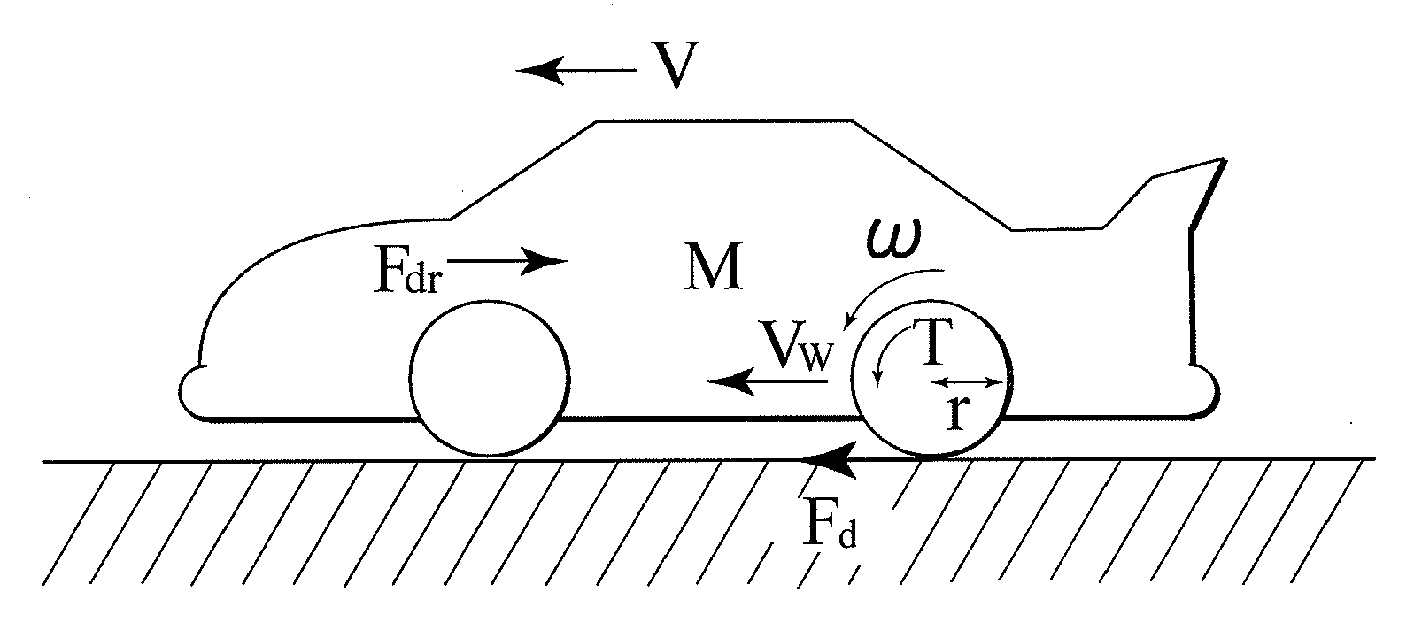
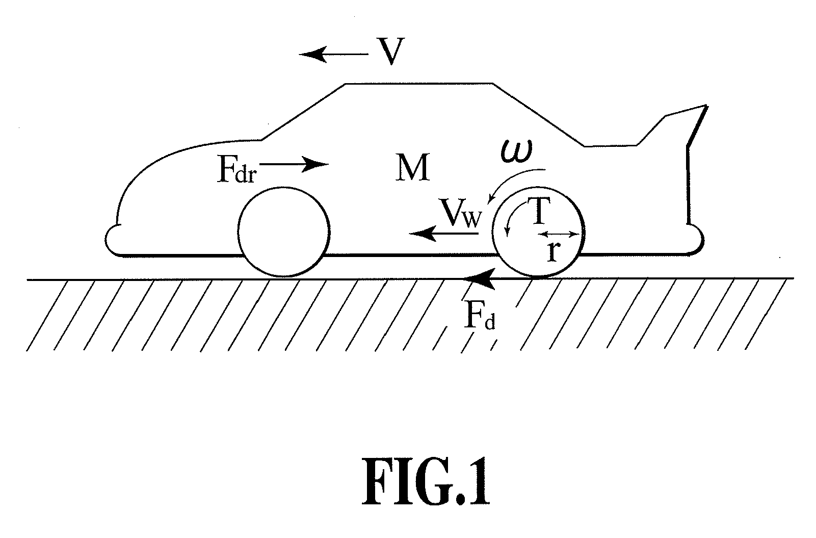
[0088]First, parameters dominating the motion of the vehicle will be considered. FIG. 1 shows forces acting on the vehicle. In this case, it is assumed that the motor has a very small time constant and that driving resistance is very small. In this case, an equation of motion for the vehicle is expressed by:

[Formula 31]

Jω{dot over (ω)}=T−rFd  (1)

[Formula 32]

M{dot over (V)}=Fd−Fdr  (2)

[Formula 33]

Vw=rω  (3)

[0089]Variables in these formulae are the rotation speed ω of the wheels, a body speed V, a wheel speed Vω, a motor torque T, a driving force Fd, and driving resistance Fdr. Constants in the above-described formulae are body weight M, a tire radius r, an inertia moment Jω of a wheel rotating portion. Reference character s denotes differentiation.

[0090]Furthermore, as a function of V and Vω, a slip ratio λ can be expressed by:

[Formula34]λ=Vw-Vmax(Vw,V,ε).(4)

[0091]However, during driving, max (Vω, V)=Vω, and during braking, max (Vω, V)=V. Furthermor...

embodiment 2

[0149]With the first SRE according to the Embodiment 1, described above, given only the driving period, during which the rotation speed ω of the wheels is positive, when the rotation acceleration of the wheels:

{dot over (ω)}  [Formula 88]

becomes negative, the estimation error may disadvantageously expand. If the condition of the vehicle becomes unstable to expand the error while the rotation speed ω of the wheels is high, then even when the condition is stabilized, a long time is required to converge the error. The present embodiment performs slip ratio control using a second SRE, to compensate for the unstable region.

2.1 Second SRE

[0150]As described above, the estimation error e (t) defined by Formula (10) does not converge monotonously in the region in which:

ω.ω<0.[Formula89]

To compensate for the unstable region, a slip ratio observer (SRO) is added to Formula (9) as a compensation item as follows:

[Formula90]λ^.=-ω.ωλ^+(1+Jωr2M)ω.ω-Tr2Mω+k(λ^)(V.-V^.)(27)

[0151]Based on Formulae...

embodiment 3

3.1 Nonlinear Control Based on Feedback Linearization

[0170]The slip ratio control used in Embodiments 1 and 2 may make an error owing to the linearization in Formula (12). Thus, the slip ratio control according to the present embodiment controls the slip ratio by performing nonlinear control based on feedback linearization.

[0171]Based on (8), by incorporating the following formula into a minor loop for nonlinear compensation, characteristics from slip ratio λ to slip ratio νcan be linearized into:

{dot over (λ)}=ν  [Formula 123]

[Formula124]T*=r2Mω(-ω.ωλ+(1+Jωr2M)ω.ω+V)(38)

[0172]The processing in FIG. (38) is defined as a nonlinear compensator. Furthermore, the present embodiment uses a proportional controller. Thus, the following formula holds true.

[Formula 125]

λ=ν≡Kp(λ*−λ)  (39)

[0173]Consequently, Formula (39) can be modified into such a 1st-order lag system as expressed by:

[Formula126]λ=Kps+Kpλ*.(40)

[0174]FIG. 19 shows a block diagram of third slip ratio control according to Embodi...


PUM


Abstract

The present invention provides a slip rate estimating device measuring a slip ratio without the need for a body speed and a slip ratio control device using the slip ratio estimating device. A motor torque measured by a torque measuring instrument is input to each of a vehicle model (601) and an SRE (602) that performs calculations including time differentiation of the slip ratio. The vehicle model (601) derives a wheel rotation speed, a wheel rotation acceleration, and a body speed. The vehicle model (601) outputs the wheel rotation speed and the wheel rotation acceleration to the SRE (602). The SRE (602) outputs the slip ratio based on the motor torque, the wheel rotation speed, and the wheel rotation acceleration.

Description

TECHNICAL FIELD[0001]The present invention relates to a slip ratio estimating device and a slip ratio control device, and more specifically, to a slip ratio estimating device and a slip ratio control device which do not use a body speed.BACKGROUND ART[0002]Electric vehicles (EVs) have advantages over current internal combustion engine vehicles (ICEVs) in that the EV helps solve energy problems and environmental problems and offers a torque response several hundred times as quick as that of the ICEV, enabling a generated torque to be accurately determined. These advantages relate to a motor and are inherent in the electric vehicle, which utilizes a motor as a driving force. Paying much attention to these advantages enables vehicle control that is impossible for the ICEV. Efforts have also been made to perform traction control based on these advantages of the motor (see Non-Patent Documents 1 and 2).[0003]Measurement of a body speed is essential for measuring a slip ratio that is an i...

Claims


Application Information

Patent Timeline
IPC IPC(8): B60L15/20B60W30/02B60W40/064B60W40/10H02P29/00
CPCB60L3/10B60L2240/443B60L2240/461B60L2240/465B60T8/175Y02T10/7258B60T2250/04B60T2270/86B60W30/18172B60W2510/0657B60W2520/28B60T8/17616Y02T10/72B60W50/0097
Inventor FUJIMOTO, HIROSHIFUJII, KIYOSHI
Owner NAT UNIV CORP YOKOHAMA NAT UNIV
Why Eureka
Try Eureka