Biological optical measuring instrument
a technology of optical measuring instruments and biological fibers, which is applied in the field of biological fiber optical measuring instruments, can solve the problems of preventing correct measurement, preventing measurement, and unable to recognize the visual disability of the newborn, and achieves the effect of enhancing the efficiency of contact work of optical fibers with the subject, facilitating contact, and correct performing biological fiber optical measuremen
- Summary
- Abstract
- Description
- Claims
- Application Information
AI Technical Summary
Benefits of technology
Problems solved by technology
Method used
Image
Examples
embodiment 1
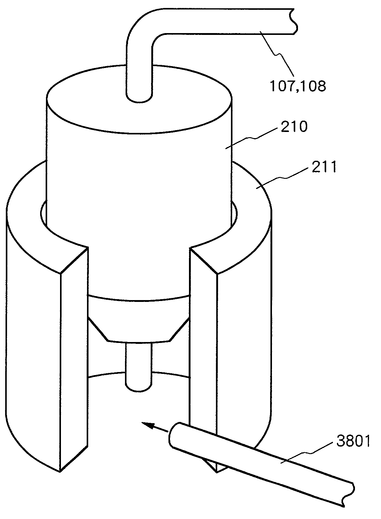
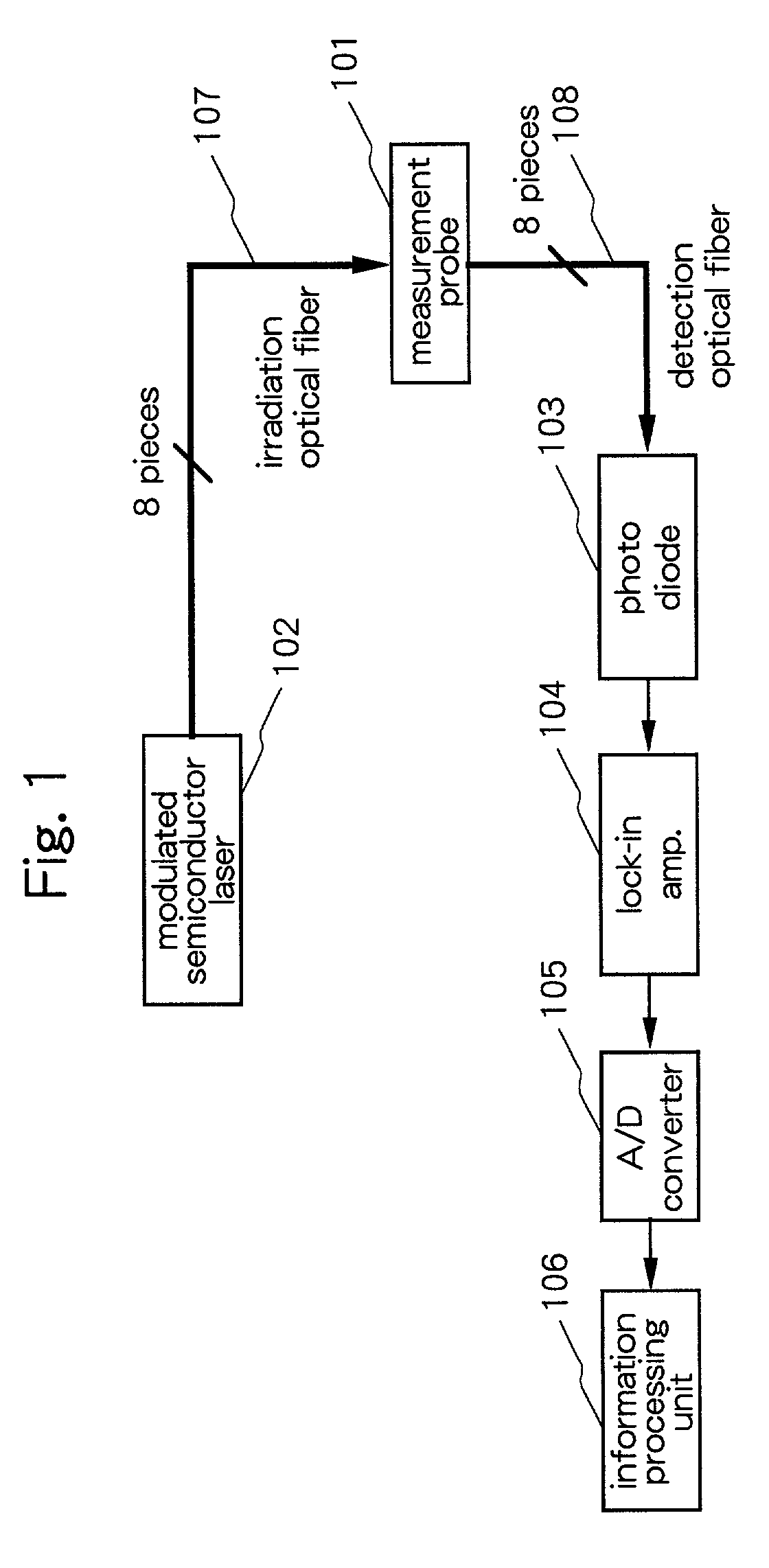
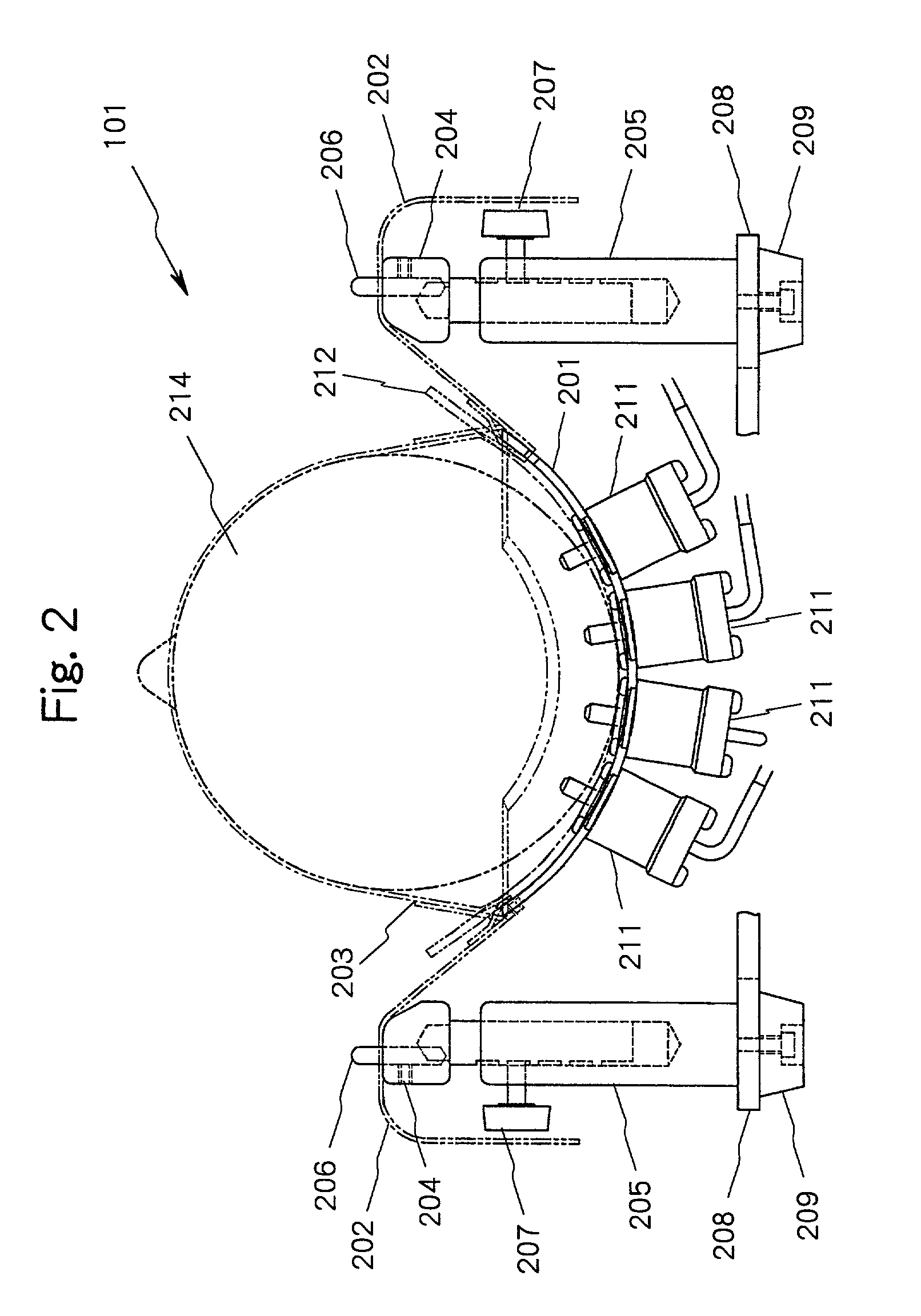
[0089]FIG. 1 is a diagram for explaining a schematic constitution of a biological optical measurement instrument representing embodiment 1 according to the present invention 101 shows a measurement probe, 102 a modulated semiconductor laser, 103 a photo diode, 104 a lock-in amplifier, 105 an A / D converter, 106 an information processing unit, 107 irradiation use optical fibers, and 108 detection use optical fibers, wherein for the means and mechanism other than the measurement probe 101, well known conventional means and mechanisms are used. Further, the embodiment 1 shows a biological optical measurement instrument which images inside a brain by irradiating light beams onto the skin of the head of a newborn and detecting the same while keeping the body position of the newborn as a subject in lateral decubitus and wherein 24 measuring points are given which are defined by the intermediate points between irradiation and detection (signal reception) points.
[0090]In FIG. 2, the measurem...
embodiment 2
[0124]FIG. 8 is a front view for explaining a schematic constitution of a measurement probe 101 for a biological measurement instrument representing embodiment 2 according to the present invention, FIG. 9 is a top view for explaining a schematic constitution of the measurement probe 101 for a biological optical measurement instrument representing the embodiment 2 according to the present invention, and FIG. 10 is a side view for explaining a schematic constitution of the measurement probe for a biological optical measurement instrument representing the embodiment 2 according to the present invention. However, in the following only the portion of the measurement probe 101 of which structure is different from that in the biological optical measurement instrument of embodiment 1 will be explained.
[0125]In FIGS. 8 through 10, 601 shows a first pillow base, 602 a second pillow base, 603 a rubber plate, 604 a mirror, 605 a first silicone rubber plate, 606 a second silicone rubber plate, 6...
embodiment 3
[0149]FIG. 12 is a vertical cross sectional side view for explaining a schematic constitution of a measurement probe 101 in a biological optical measurement instrument representing embodiment 3 according to the present invention; FIG. 13 is a top view for explaining a schematic constitution of a measurement probe 101 in a biological optical measurement instrument representing the embodiment 3 according to the present invention; and is a side view for explaining a schematic constitution of a measurement probe 101 in a biological optical measurement instrument representing the embodiment 3 according to the present invention. However, in the following explanation, only the part of the measurement probe 101 which is different from the biological optical measurement instrument according to the embodiment 1 will be explained. Further, in order to simplify the explanation, a case wherein respective 2 pieces of irradiation use optical fibers 107 and the detection use optical fiber 108 are i...
PUM
| Property | Measurement | Unit |
|---|---|---|
| thickness | aaaaa | aaaaa |
| time | aaaaa | aaaaa |
| thickness | aaaaa | aaaaa |
Abstract
Description
Claims
Application Information
 - R&D
- Intellectual Property
- Life Sciences
- Materials
- Tech Scout
- Unparalleled Data Quality
- Higher Quality Content
- 60% Fewer Hallucinations
Browse by: Latest US Patents, China's latest patents, Technical Efficacy Thesaurus, Application Domain, Technology Topic, Popular Technical Reports.
© 2025 PatSnap. All rights reserved.Legal|Privacy policy|Modern Slavery Act Transparency Statement|Sitemap|About US| Contact US: help@patsnap.com


